Cardiovascular medicine effusion drainage device

A cardiovascular and effusion technology, applied in the field of effusion drainage devices in cardiovascular medicine, can solve problems such as inability to drain fluid shunting and pain, and achieve the effects of ensuring smooth continuity, reducing pain, and reducing work difficulty

Active Publication Date: 2021-05-25
南通市传染病防治院
View PDF10 Cites 0 Cited by
  • Summary
  • Abstract
  • Description
  • Claims
  • Application Information

AI Technical Summary

Problems solved by technology

[0005] For example, the Chinese patent with the invention number of 201710550425.3 discloses a multifunctional drainage device for cardiovascular medicine, including a negative pressure suction bottle (1), characterized in that: the top of the negative pressure suction bottle (1) passes through the connecting mechanism (15 ) is connected with fixture (16), and the top of negative pressure suction bottle (1) is equipped with open source single-chip microcomputer (5) by installation frame (4), and the top of described negative pressure suction bottle (1) is communicated with drainage pipe (2) A flow control valve (3) is installed at the connection between the drainage tube (2) and the negative pressure suction bottle (1), and the side of the negative pressure suction bottle (1) is uniformly fixed with a clip for clamping the drainage tube (2). connection mechanism (18), the negative pressure suction bottle (1) is provided with a pressure regulator (17), and the bottom of the negative pressure suction bottle (1) is communicated with a liquid outlet pipe (14), and the liquid outlet pipe (14) is connected with the Electromagnetic valve (19) is installed at the junction of negative pressure suction bottle (1), and described open-source single-chip microcomputer (5) is electrically connected with flow control valve (3), electromagnetic valve (19) and external power supply respectively; The device reasonably controls and adjusts the pressure inside the bottle to ensure the stability of the drainage speed and relieve the patient's pain during the operation. The drainage tube is placed in a standardized manner through the clamping mechanism to facilitate its storage and storage. It will be used next time; however, the invention cannot effectively divert the drainage fluid, which ensures the smooth continuity of the drainage and makes it more painful for the patient to replace the drainage bottle
[0006] Another example is that the invention number is: 201510542637.8 Chinese patent discloses a medical drainage device, comprising a bed clamp (1), a support column (2), a fixed barrel (3) and a drainage bottle (4), characterized in that the The bed clamp (1) is C-shaped, including two parts, an upper splint (5) and a lower splint (6). The middle part of the upper surface of the upper splint (5) is provided with a support column (2), and the support column (2) The top of the top is fixedly connected with a fixed bucket (3), and the fixed bucket (3) is provided with a drainage bottle (4), and the described drainage bottle (4) includes a bottle body (21), a bottle cap (11), a drainage tube (10 ), an exhaust pipe (17) and a manual air pump (18), the bottle cap (11) is sealed and fastened on the top of the bottle body (21), and the bottle cap (11) is provided with a liquid inlet port and exhaust port, the drainage pipe (10) communicates with the liquid inlet port on the bottle cap (11), the exhaust pipe (17) communicates with the exhaust port on the bottle cap (11), and the exhaust pipe The other end of (17) is connected with manual suction pump (18); This invention is provided with adjustable height fixing frame, thereby makes the height positioning of drainage bottle accurate; Be provided with float and alarm device, can monitor drainage situation in real time, prevent liquid Overflow, etc., are convenient for patient treatment and medical personnel care, easy to carry, easy to operate and use, smooth drainage, and high safety; but this invention cannot quickly and effectively divert the drainage fluid in the drainage bottle when the fluid volume is too large. And can maintain continuity, but can not avoid the pain caused to patients due to replacement of drainage bottles

Method used


Image

  • Cardiovascular medicine effusion drainage device
  • Cardiovascular medicine effusion drainage device
  • Cardiovascular medicine effusion drainage device

Examples


Embodiment Construction

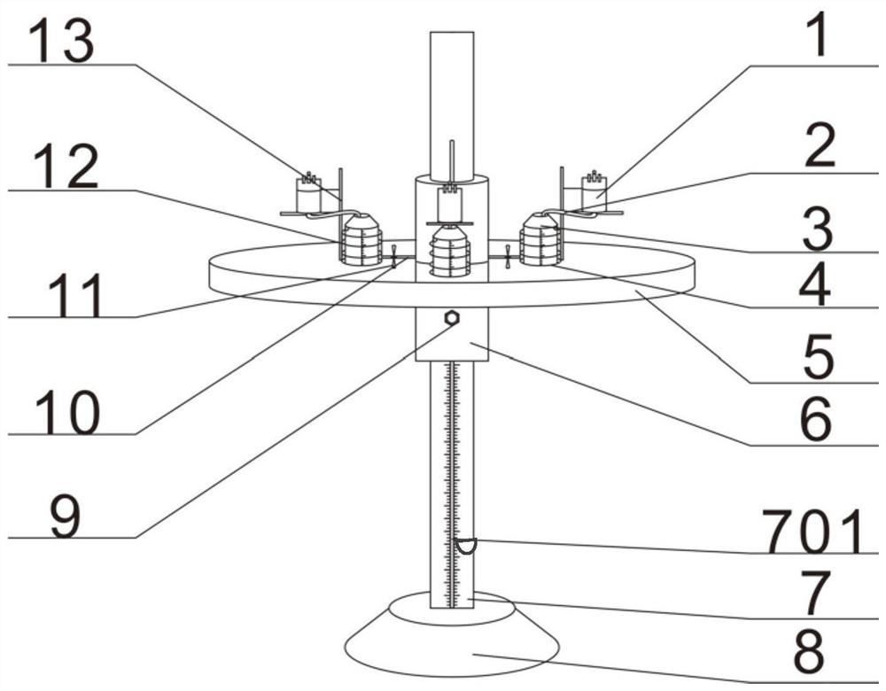
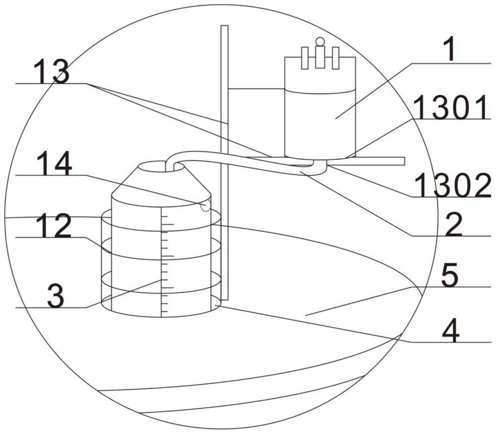
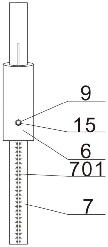
[0036] The invention provides a device for drainage of effusion in cardiovascular internal medicine with simple structure, convenient and fast use, high safety, high precision, smooth drainage and good continuity, and reduced labor intensity, which is beneficial to large-scale promotion.

[0037] In order to make the object, technical solution and advantages of the present invention clearer, the present invention will be described in further detail below in conjunction with specific embodiments and with reference to the accompanying drawings.

[0038] In an exemplary embodiment of the present invention, a device for drainage of effusion in cardiovascular medicine is provided. Such as Figure 1 to Figure 3As shown, the present invention includes a fixed frame and a drainage bottle, and the drainage bottle is fixed on the fixed frame through a connection mechanism, and the drainage bottle includes a bottle body 1 and a drainage tube, and the bottom of the bottle body is provided...


PUM


Abstract

The invention discloses a drainage device for effusion in cardiovascular medicine, which comprises a fixed frame and a drainage bottle. The drainage bottle is fixed on the fixed frame through a connecting mechanism. The shunt bottle connected to the bottom of the shunt tube; the fixed frame includes a base, a support rod, a sleeve and a support plate, and the surface of the support rod is provided with a scale groove that runs through the support rod in the horizontal direction, and a horizontal rod is fixed in the scale groove, and the horizontal rod can be moved along the The scale groove slides up and down; the sleeve is provided with a round hole that runs through the sleeve in the horizontal direction; there are at least four storage slots on the support plate, and a fixed ring with the same aperture as the storage slot is provided on the storage slot, and the side wall of the fixed ring is far away from the support rod One side is fixedly connected to the "inverted T"-shaped plate; the shunt bottle is set in the storage tank, and the bottle body is set on the upper surface of the "inverted T"-shaped plate; the invention has simple structure, convenient and quick use, high safety, and high precision. The drainage is smooth and continuous, and the labor intensity is reduced.

Description

technical field [0001] The invention relates to the technical field of drainage devices, in particular to a drainage device for effusion in cardiovascular medicine. Background technique [0002] At present, the negative pressure drainage bottle is a conventional medical device, which is used as an external drainage device for drainage of blood, fluid or secretions in the operation cavity during or after the operation. The existing negative pressure drainage bottle usually includes a bottle body, a bottle cap and a drainage tube. The bottle cap is usually provided with two interfaces, namely the liquid inlet interface and the negative pressure interface. During operation, one end of the drainage tube is enclosed in the inlet of the bottle cap. On the liquid port, the other end of the drainage tube is placed on the drainage part, and the negative pressure port on the bottle cap is connected to the negative pressure suction device through the negative pressure connection tube, ...

Claims


Application Information

Patent Timeline
Patent Type & Authority Patents(China)
IPC IPC(8): A61M1/00
CPCA61M1/0023A61M2205/3389A61M1/61
Inventor 黄春雨钱湘云王美兰
Owner 南通市传染病防治院
Why Eureka
Try Eureka