Thermoelectric decoupling type thermal energy storage heat and power combined supply system

A technology of combined heat and power supply and thermal energy storage, which is applied in the direction of combined combustion mitigation, steam engine installation, steam application, etc., can solve the problems of inability to store heat in the system and low energy conversion efficiency, so as to ensure reliability, improve reliability, and ensure The effect of stability

Pending Publication Date: 2018-12-18
中国船舶重工集团公司第七0三研究所
View PDF0 Cites 1 Cited by
  • Summary
  • Abstract
  • Description
  • Claims
  • Application Information

AI Technical Summary

Problems solved by technology

[0005] The purpose of the present invention is to provide a thermoelectric decoupling thermal energy storage combined heat and power system in order to overcome the problems in the prior art that failure of power supply or electric heating related equipment will cause the system to fail to store heat and the energy conversion efficiency is low

Method used


Image

  • Thermoelectric decoupling type thermal energy storage heat and power combined supply system

Examples


specific Embodiment approach 1

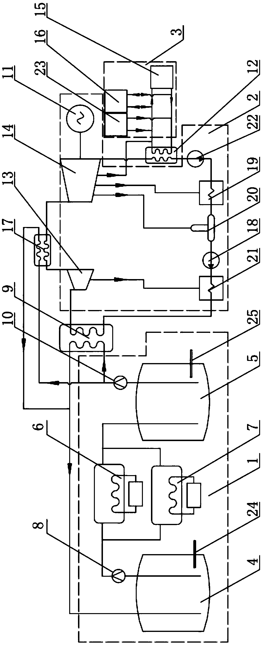
[0015] A thermoelectric decoupling thermal energy storage cogeneration system of the present invention includes an energy storage power station unit 1 , a steam turbine unit 2 and a heat supply unit 3 .

[0016] The energy storage power station unit 1 includes a low-temperature medium tank 4, a high-temperature medium tank 5, an electric heater 6, and a gas heater 7. Both the low-temperature medium tank 4 and the high-temperature medium tank 5 store heat storage medium; the low-temperature medium tank 4 A low-temperature medium output pipeline is connected, and the low-temperature medium output pipeline passes through the heating ends of the electric heater 6 and the gas heater 7 respectively and then enters the high-temperature medium tank 5; the low-temperature medium output pipeline is provided with a cold medium pump 8 for For pumping low-temperature heat storage medium;

[0017] The high-temperature medium tank 5 is connected with a high-temperature medium output pipeline...

specific Embodiment approach 2

[0025] The difference between the second embodiment and the first embodiment is that the heat storage medium is molten salt.

[0026] The molten salt can use NaNO with a mass fraction of 60% respectively 3 and 40% KNO 3 The binary molten salt made by mixing, the melting point of the binary molten salt is about 220°C, and the upper limit expansion temperature is 500°C; or KNO with a mass fraction of 53% respectively 3 , 40% NaNO 2 and 7% NaNO 3 Mixed ternary molten salt. The melting point of ternary molten salt is 142°C and the vaporization point is 500°C. Sodium nitrite will decompose slowly above 450°C, but the working temperature of the general system is within 250-350°C.

specific Embodiment approach 3

[0027] The difference between the third embodiment and the first embodiment is that a high-pressure exhaust steam pipeline is connected between the high-pressure cylinder 13 of the steam turbine and the medium-low pressure cylinder 14 of the steam turbine; There is a reheater 17, and the high-temperature medium output pipeline also performs heat exchange with the high-pressure exhaust pipeline through the reheater 17.

[0028] The high-temperature medium output pipeline is divided into two paths, one path returns to the low-temperature medium tank 4 after passing through the steam generator 9, and the other path returns to the low-temperature medium tank 4 after passing through the reheater 17.

[0029] After the steam does work in the high-pressure cylinder 13 of the steam turbine, and then passes through the reheater 17 to exchange heat with the high-temperature heat storage medium from the high-temperature medium tank 5, the steam enters the medium-low pressure cylinder 14 o...


PUM


Abstract

The invention discloses a thermoelectric decoupling type thermal energy storage heat and power combined supply system, and relates to heat and power combined supply systems. The problem that in the prior art, power source power supply or electric heating related equipment fails, and the system cannot store heat is solved. The system comprises an energy storage power station unit, a steam turbine unit and a heat supply unit; the energy storage power station unit comprises a low-temperature medium tank, a high-temperature medium tank, an electric heater and a gas heater, heat storage media are stored in the low-temperature medium tank and the high-temperature medium tank, the low-temperature medium tank is connected with a low-temperature medium output pipeline, the low-temperature medium output pipeline passes through heating ends of the electric heater and the gas heater and then enters the high-temperature medium tank, and a cooling medium pump is arranged on the low-temperature medium output pipeline and used for pumping low-temperature heat storage media. The gas heater in parallel connection with the electric heater is arranged, and when the power source power supply or electric heating related equipment fails, the gas heater can be used in a switched manner.

Description

technical field [0001] The invention relates to a combined heat and power system, in particular to a thermoelectric decoupling type combined heat and power system. Background technique [0002] In the prior art "Independent Molten Salt Heat Storage Power Station Technology and Its Evaluation", it is disclosed that in order to solve the intermittent and unstable power generation of renewable energy and the problem of "low power" in the power grid, the molten salt is heated by converting excess electric energy into heat energy With the advantages of heat storage, it converts low-quality electricity into high-quality electricity and realizes the consumption of excess electricity. But the defective of this prior art is: [0003] 1. If the power supply or electric heating related equipment fails, the system will not be able to store heat, and the reliability of power generation and heating cannot be guaranteed; [0004] 2. If the heat is stored during the "low valley" period of...

Claims


Application Information

Patent Timeline
Patent Type & Authority Applications(China)
IPC IPC(8): F01K11/02F01K13/00F01K17/02F01D15/10
CPCF01D15/10F01K11/02F01K13/00F01K17/025Y02E20/14Y02E20/16
Inventor 顾阳苗强刘晓宇韩双刘宇阳
Owner 中国船舶重工集团公司第七0三研究所
Why Eureka
Try Eureka