Eureka AIR delivers breakthrough ideas for toughest innovation challenges, trusted by R&D personnel around the world.

Airflow guide reversing valve structure for circulating homogenizing device for foam materials and bottle flakes

A technology of a homogenizing device and a reversing valve, which is applied in the valve shell structure, valve device, valve operation/release device, etc., can solve problems such as affecting fiber quality, and achieve the effect of concise overall structure, convenient assembly and convenient production.

Active Publication Date: 2018-12-18
CHANGSHU GOLD SPRING CHEM FIBERS & KNITTINGS
View PDF20 Cites 1 Cited by
  • Summary
  • Abstract
  • Description
  • Claims
  • Application Information

AI Technical Summary

Problems solved by technology

However, if multiple batches of homogenized raw materials are combined, although the output of fibers spun from the same batch can be increased, as mentioned above, the fiber quality will be seriously affected due to the differences in raw materials of different batches.

Method used


Image

  • Airflow guide reversing valve structure for circulating homogenizing device for foam materials and bottle flakes
  • Airflow guide reversing valve structure for circulating homogenizing device for foam materials and bottle flakes
  • Airflow guide reversing valve structure for circulating homogenizing device for foam materials and bottle flakes

Examples


Embodiment Construction

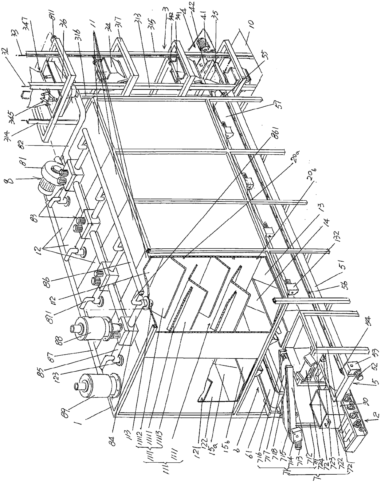
[0025] In the following descriptions, all concepts related to directionality or orientation of up, down, left, right, front and back are based on image 3 The shown position status is a reference, so it cannot be understood as a special limitation on the technical solution provided by the present invention. For example Figure 9 and Figure 10 The left, right, front and back of the position shown are exactly the same as image 3 In contrast to the position status, the applicant is in the Figure 9 and Figure 10 When explaining, still use image 3 The current position status is the reference.

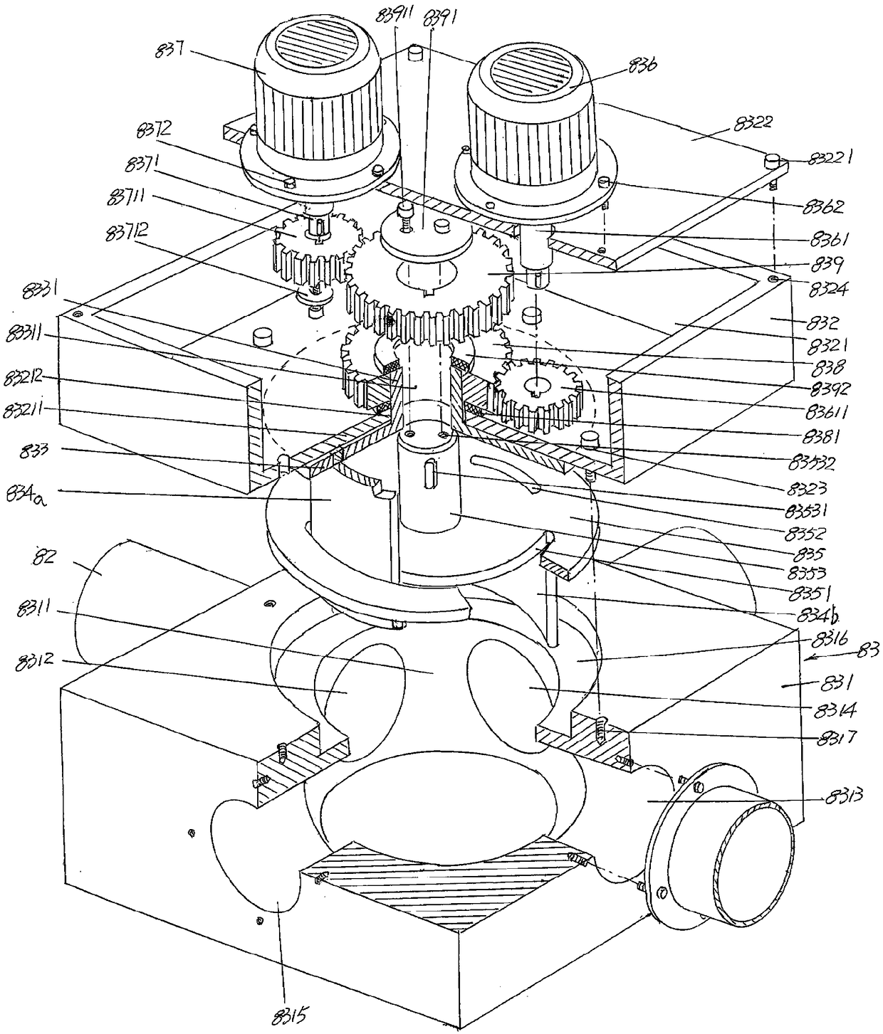
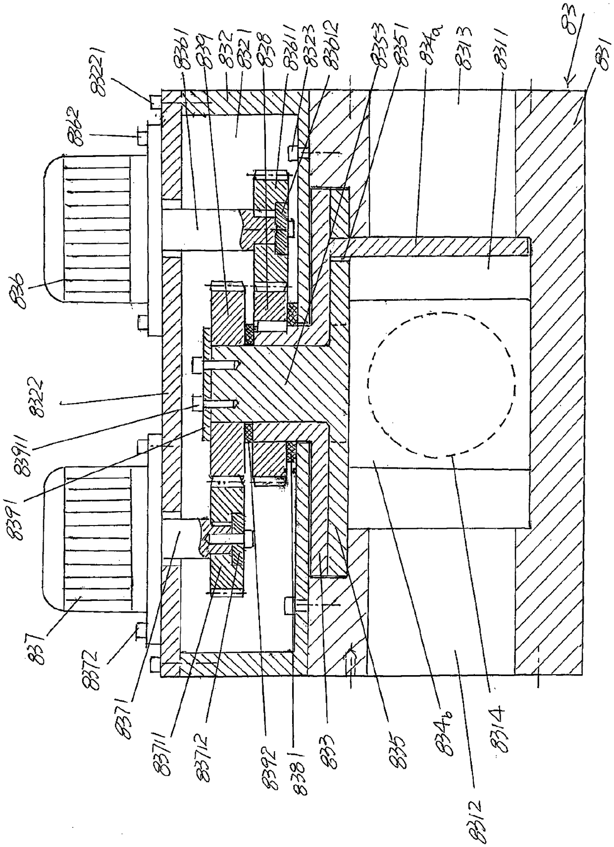
[0026] See figure 1 and figure 2, shows the air flow guide material reversing valve assembly 83, the air flow guide material reversing valve assembly 83 includes a valve seat 831, a gear box 832, an upper valve disc 833, an arc-shaped upper valve 834a, a lower valve disc 835, an arc-shaped lower valve disc The valve 834b, the upper valve disc drive motor 836, the lower valve di...


PUM


Abstract

The invention relates to an airflow guide reversing valve structure for circulating homogenizing device for foam materials and bottle flakes, and belongs to the technical field of a textile raw material mixing device. The airflow guide reversing valve structure comprises an airflow guide reversing valve assembly, and the airflow guide reversing valve assembly comprises a valve seat, a gear case, an upper valve disk, an upper arc-shaped valve, a lower valve disk, a lower arc-shaped valve, upper and lower valve disk driving motors and upper and lower valve disk gears. A valve turning chamber isformed in the center of the valve seat, and a valve seat feeding hole, a first valve seat discharging hole, a second valve seat discharging hole and a third valve seat discharging hole are formed in the valve seat. A valve disk turning chamber is formed in the center of the upper part of the valve seat. A gear case is fixed to the valve seat, and a gear case cover is arranged at the upper part ofa gear case chamber. The upper valve disk is positioned on one downward side of the bottom wall of the gear case chamber, and the lower valve disk is supported on the valve disk turning chamber. The upper and lower valve disk driving motors are fixed onto the gear case cover, the upper valve disk gear is positioned in the gear case chamber, and the lower valve disk gear is fixed onto a center shaft of the lower disk in a sleeved mode. The airflow guide reversing valve structure has the advantages of simple integral structure, convenience in manufacturing and assembly, small volume, light weight and reliable and stable action and is convenient to assemble with a homogenizing silo.

Description

technical field [0001] The invention belongs to the technical field of textile raw material mixing devices, and in particular relates to a structure of an airflow diverting material reversing valve of a foam material and bottle flake circulation homogenization device. Background technique [0002] The foam material mentioned above is also called "foam material", also known as "PET foam material". Recycled polyester bottle fragments suitable for the production of short fibers or filaments obtained by processing recycled polyester bottles; the above-mentioned "air flow reversing valve structure" can also be called "reversing valve structure". [0003] As the industry knows, due to the different origins, batches, and manufacturers of polyester bottles, when manufacturers of textile staple fibers or textile filaments purchase polyester bottle flakes from the market, they must use the same origin, the same batch, and The amount of PET bottle fragments obtained after recycling PE...

Claims


Application Information

Patent Timeline
Patent Type & Authority Applications(China)
IPC IPC(8): F16K11/08F16K31/04F16K31/53F16K27/06
CPCF16K11/08F16K27/06F16K31/04F16K31/53Y02W30/62
Inventor 李文俊樊海彬刘薇樊慧斌王维平
Owner CHANGSHU GOLD SPRING CHEM FIBERS & KNITTINGS
Why Eureka
Eureka Blog
Learn More