
Boiler waste heat collector

A boiler waste heat and heat collector technology, applied in fluid heaters, lighting and heating equipment, reducing greenhouse gases, etc., can solve the problems of boiler recovery, waste, and reduced equipment practicability, so as to save energy costs and ensure sealing High efficiency, good effect of waste heat recovery

Active Publication Date: 2018-12-18
YIYANG TEA FACTORY
View PDF20 Cites 0 Cited by
  • Summary
  • Abstract
  • Description
  • Claims
  • Application Information

AI Technical Summary

Problems solved by technology

[0003] However, there are a large number of shortcomings in the existing boiler heat collector equipment for tea production. For example, the existing boiler waste heat collector equipment cannot recover the waste heat produced by the boiler well, so that serious waste is caused, and Existing boiler heat collector heat exchange tubes are inconvenient to disassemble. If the heat exchange tubes are used for a long time, a large amount of smoke and waste dust will accumulate inside the heat exchange tubes, so that heat exchange cannot be performed better, thereby greatly reducing the practicality of the equipment

Method used


Image

  • Boiler waste heat collector
  • Boiler waste heat collector
  • Boiler waste heat collector

Examples


Embodiment Construction

[0026] The present invention will be further described below in conjunction with the accompanying drawings and embodiments.

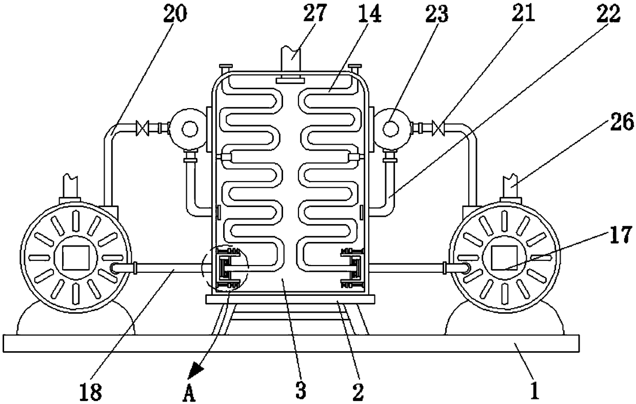
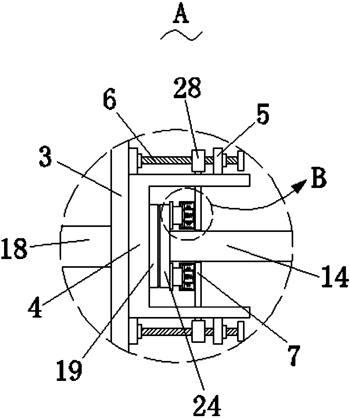
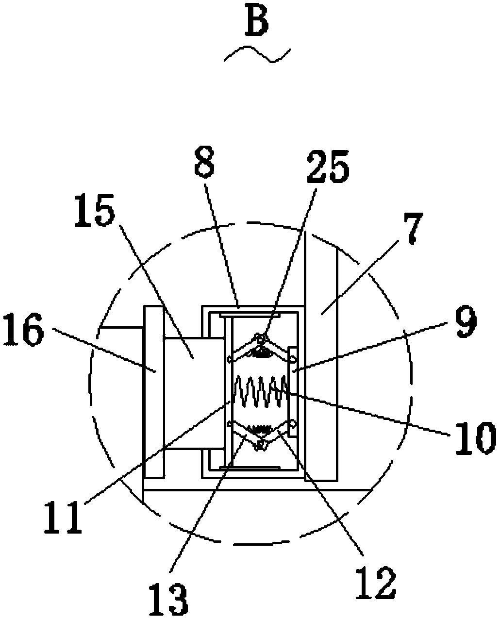
[0027] Please refer to figure 1 , figure 2 and image 3 ,in, figure 1 A schematic structural diagram of a preferred embodiment of the boiler waste heat collector provided by the present invention; figure 2 for figure 1 The enlarged schematic diagram of part A shown; image 3 for figure 2 The enlarged schematic diagram of part B is shown. The boiler waste heat collector includes: a bottom plate 1; a support frame 2, the support frame 2 is fixed on the top of the bottom plate 1; a preheating chamber 3, the bottom of the preheating chamber 3 is fixed on the top of the support frame 2 Two U-shaped blocks 4, two U-shaped blocks 4 are respectively fixed on both sides of the inner wall of the preheating chamber 3, and both sides of the top and bottom of the U-shaped block 4 are fixedly connected with a fixed plate 5 A threaded rod 6 is rotatably con...


PUM


Abstract

The invention provides a boiler waste heat collector. The boiler waste heat collector comprises a bottom plate, a support frame fixed to the top of the bottom plate, a preheating bin and two U-shapedblocks, wherein the bottom of the preheating bin is fixed to the top of the support frame; the two U-shaped blocks are fixed to the two sides of the inner wall of the preheating bin correspondingly; fixing plates are fixedly connected with the two sides of the tops and bottoms of the U-shaped blocks; and a threaded rod is rotationally connected between the opposite sides of the two fixing plates through bearings. Through the boiler waste heat collector provided by the invention, a water source in the preheating bin can be well heated in advance, the boiler waste heat collector has a good wasteheat recovery function, and thus a large amount of energy cost is reduced; and a heat conduction pipe can be dismounted, thus, the heat conduction pipe is convenient to clean and maintain so that heat exchange with cold water in the preheating bin can be better ensured, and the practicability of the waste heat recovery equipment is improved.

Description

technical field [0001] The invention relates to the technical field of tea processing waste heat recovery equipment, in particular to a boiler waste heat collector. Background technique [0002] The boiler is a kind of energy conversion equipment. The energy input to the boiler includes chemical energy and electric energy in the fuel. The boiler outputs steam, high-temperature water or organic heat carrier with a certain amount of heat energy. The original meaning of the pot refers to the water container heated on the fire. The furnace refers to the place where fuel is burned. The boiler includes two parts: the pot and the furnace. The combustion and heat absorption and evaporation of the shell boiler are completed in a cylinder. It can be divided into horizontal and vertical, such as the early development of Lan , firecracker stove and so on. The water tube boiler is a boiler whose main heating surface is a tube. It is a major improvement of the early boilers. The power u...

Claims


Application Information

Patent Timeline
Patent Type & Authority Applications(China)
IPC IPC(8): F24H9/00F23J15/06
CPCF23J15/06F24H9/0005Y02E20/30
Inventor 姚坚张汉成文卫安茂强
Owner YIYANG TEA FACTORY
Learn More