A control method of a centrally powered electrical impedance imaging electrode system

A technology of electrical impedance imaging and electrode system, which is applied in the direction of material resistance, and can solve problems such as interruption of connection between electrodes and the system, affecting measurement results, and instability

Active Publication Date: 2020-08-18
TIANJIN UNIV
View PDF4 Cites 0 Cited by
  • Summary
  • Abstract
  • Description
  • Claims
  • Application Information

AI Technical Summary

Problems solved by technology

This method is unstable in actual use. For example, a loose interface or a damaged wire will cause the interruption of the connection between the electrode and the system, affecting the measurement results, and it is not easy to locate the faulty electrode.

Method used


Image

  • A control method of a centrally powered electrical impedance imaging electrode system
  • A control method of a centrally powered electrical impedance imaging electrode system
  • A control method of a centrally powered electrical impedance imaging electrode system

Examples


Embodiment Construction

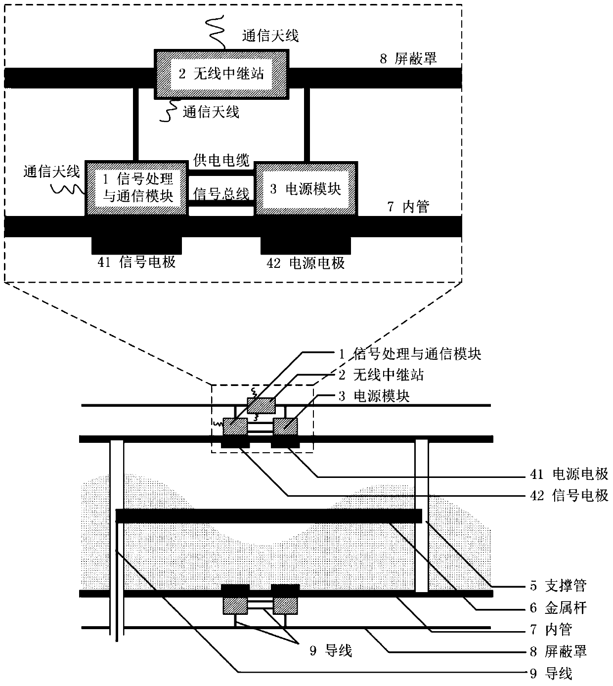
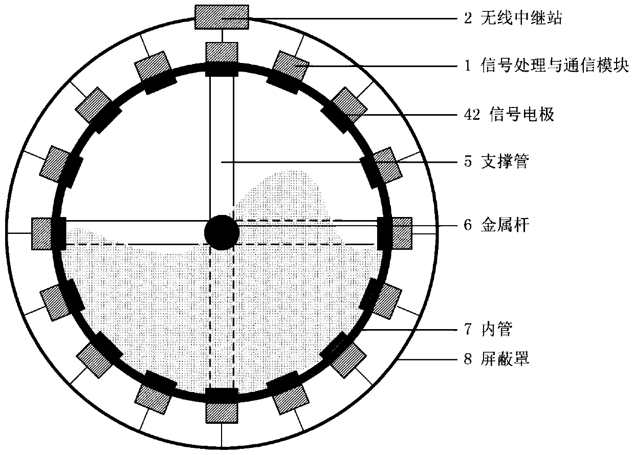
[0018] The electrical impedance imaging measurement device to which the electrode system control method of the present invention is applied will be described in detail below with reference to the accompanying drawings and embodiments.

[0019] 1. System structure

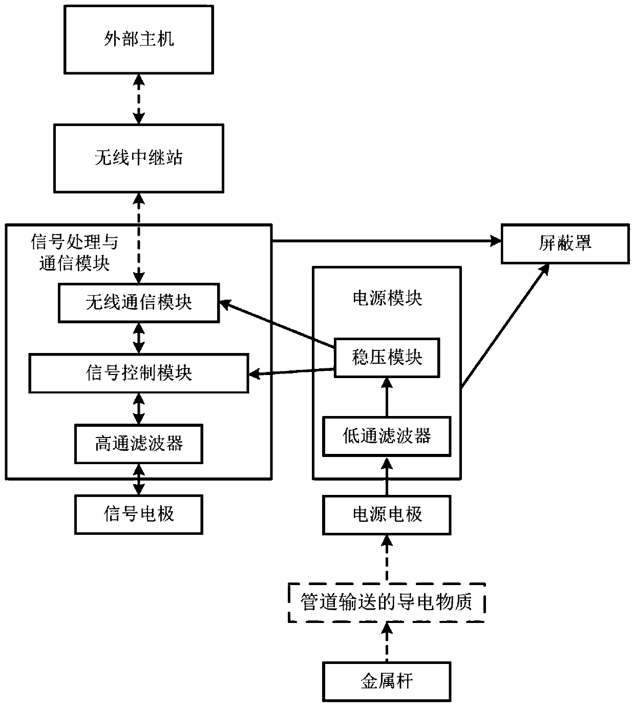
[0020] In this design, the measuring instrument needs to be installed on a horizontal pipeline. The material conveyed in the pipeline is a conductive material (usually a conductive liquid), and the material should pass through the conductive metal pipe in the center of the pipeline and be in contact with the central metal rod and at least one edge electrode To ensure the formation of a current loop. The electrodes are distributed in two layers, one is the power supply electrode, and the other is the signal electrode. The signal electrode is connected with the signal module, and the power supply electrode is connected with the power module. The power module supplies power to the signal module through the power supply cab...


PUM


Abstract

The invention relates to a control method of a centralized power supply type electric impedance imaging electrode system. The electrode system comprises a plurality of electrode units, wherein each electrode unit comprises a signal electrode, a power supply electrode, a wireless communication module, a power supply module, a signal control module, a high-pass filter, a signal excitation and measurement unit. The control method of each electrode unit comprises the following steps that the signal control module of the electrode unit controls the switching of a excitation state and a measurementstate of the signal electrode according to a received external wireless signal; a signal excitation and measurement module generates a high-frequency signal under an excited state of the electrode unit, and transmits the high-frequency signal to the signal electrode through the high-pass filter, so that the signal electrode is in an excitation state; and the signal electrode is in a measurement state under a measurement state of the electrode unit, high-frequency excitation signals of the other electrodes is transmitted to the signal electrode through an in-tube conducting medium, and is inputted to the signal excitation and measurement module though the high-pass filter to obtain a measurement result.

Description

Technical field [0001] The invention relates to a center-powered electrical impedance imaging measurement device based on wireless communication. Background technique [0002] Electrical impedance tomography (EIT) technology is a process detection technology developed based on electromagnetic field theory. It has the advantages of non-invasive, high real-time, low cost, etc., and is widely used in industrial and medical fields. In the EIT detection process, a group of electrode arrays are uniformly installed or placed on the boundary of the object to be tested. In the detection process, a current or voltage signal is applied to one or more electrodes, the electrical signals of other electrodes are detected, and the conductivity distribution image is reconstructed through an image reconstruction algorithm. Since the EIT detection process requires the existence of a current loop, it is necessary to ensure that the measured medium is a conductive substance. [0003] In the electric ...

Claims


Application Information

Patent Timeline
Patent Type & Authority Patents(China)
IPC IPC(8): G01N27/04
CPCG01N27/04
Inventor 王泽莹岳士弘刘笑远
Owner TIANJIN UNIV
Why Eureka
Try Eureka