A high-power optical fiber end cap and its manufacturing method

A fiber-end, high-power technology, applied in the field of fiber lasers and laser transmission systems, can solve the problems of end cap damage, difficult to guarantee fusion quality, small core area, etc., to avoid energy loss, reduce optical power density, reduce The effect of light reflection

Active Publication Date: 2020-03-31
JIANGSU UNIV
View PDF5 Cites 2 Cited by
  • Summary
  • Abstract
  • Description
  • Claims
  • Application Information

AI Technical Summary

Problems solved by technology

[0005] High-power fiber laser end caps are usually composed of an optical fiber and a large-diameter quartz cone rod. However, the size difference between the quartz cone rod and the optical fiber is large, which makes it difficult to control the temperature during fusion. Therefore, the quality of the fusion is difficult to guarantee.
At the same time, the core area of ​​the single-mode fiber is small, and the optical power density on the output surface is high, so it is very easy to generate a strong temperature rise due to the tiny defect of the fusion joint, which in turn leads to damage to the end cap.
Using a tapered quartz rod to weld the optical fiber to the thin end of the tapered quartz rod can solve this problem to a certain extent, but because the diameter of the thin end of the quartz rod is still much larger than the diameter of the optical fiber, there are still difficulties in welding, Disadvantages such as high optical power density at the welding point

Method used


Image

  • A high-power optical fiber end cap and its manufacturing method
  • A high-power optical fiber end cap and its manufacturing method
  • A high-power optical fiber end cap and its manufacturing method

Examples


Embodiment Construction

[0039] The present invention will be further described below in conjunction with the accompanying drawings and specific embodiments, but the protection scope of the present invention is not limited thereto.

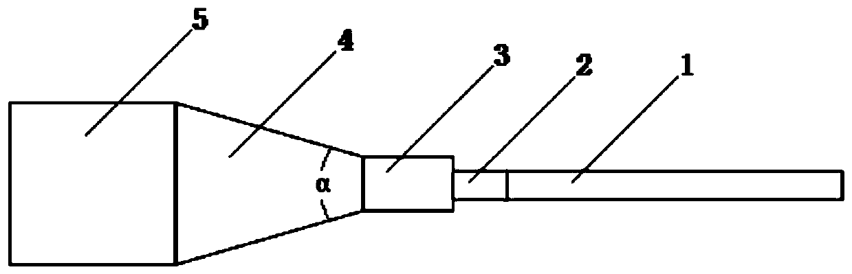
[0040] Such as figure 1 As shown, a high-power optical fiber end cap according to the present invention includes a double-clad optical fiber 1 coaxially arranged, a coreless optical fiber 2 and a quartz rod, and the quartz rod includes a first cylindrical section 3 connected coaxially in sequence , Conical frustum section 4 and second cylindrical section 5, the diameter of an end surface of said conical frustum section 4 and the diameter D of first cylindrical section 3 1 Identical, the diameter of the other end face of described frustum segment 4 is the same as the diameter D of second cylindrical segment 5 2 Same, the diameter D of the first cylindrical section 3 1 smaller than the diameter D of the second cylindrical segment 5 2 , one end of the double-clad fiber 1 ...


PUM

PropertyMeasurementUnit
diameteraaaaaaaaaa
diameteraaaaaaaaaa
lengthaaaaaaaaaa

Abstract

The invention provides a high-power optical fiber end cap and a manufacturing method thereof. The optical fiber end cap comprises a double-clad optical fiber, a core-free optical fiber and a quartz rod which are coaxially arranged; the quartz rod comprises a first cylindrical section, a circular table section and a second cylindrical section which are coaxially connected in sequence, the diameterof the first cylindrical section is smaller than that of the second cylindrical section; the double-clad optical fiber is connected with one end of the core-free optical fiber in a welding mode, and the other end of the core-free optical fiber is connected with one end of the first cylindrical section in a welding mode; the diameter of the cladding layer of the core-free optical fiber is larger than or equal to the diameter of the double-clad optical fiber; and the diameter of the cladding layer of the core-free optical fiber is smaller than or equal to the diameter of the first cylindrical section. The laser firstly passes through the core-free optical fiber, so that energy is expanded, and the light power density in the connecting place of the output end plane and the quartz rod is lowered; by selecting the proper length of the core-free optical fiber, the output light spot can be large enough when the laser outputs from the core-free optical fiber, so that the optical power densityon the output surface can be effectively reduced; and meanwhile, energy is not output from the side surface of the core-free optical fiber, and loss of energy is avoided.

Description

technical field [0001] The invention relates to a fiber laser and a laser transmission system, in particular to a high-power fiber end cap and a manufacturing method thereof. Background technique [0002] In recent years, high-power fiber lasers have been the focus of attention in the laser field. Because of their high optical power density, good beam quality, and ease of use, they are widely used in industrial processing, weaponry, and medical equipment. The high-power laser is equipped with a high-power energy-transmitting optical cable, which can make the laser more flexible and controllable, and realize flexible three-dimensional processing; at the same time, its transmission beam quality is excellent and the optical power density is large. Since the fiber used in high-power fiber lasers is usually a double-clad fiber with a large mode field area, the core diameter is only 10μm-30μm, and the power density of the light in the fiber core is very high. It may strengthen th...

Claims


Application Information

Patent Timeline
Patent Type & Authority Patents(China)
IPC IPC(8): G02B6/255H01S3/067
CPCG02B6/2551H01S3/06708
Inventor 陈明阳何平苏鹏白彤彤
Owner JIANGSU UNIV
Why Eureka
Try Eureka