High-flatness Broadband Comb Spectrum Generator Based on PLL Mechanism

A comb spectrum generator and phase-locked loop technology, applied in pulse processing, automatic power control, pulse technology, etc., can solve problems such as difficult to meet high flatness, broadband output fine spacing, etc.

Active Publication Date: 2020-11-10
UNIV OF ELECTRONICS SCI & TECH OF CHINA
View PDF9 Cites 0 Cited by
  • Summary
  • Abstract
  • Description
  • Claims
  • Application Information

AI Technical Summary

Problems solved by technology

[0004] Nowadays, with the rapid development of the communication industry, the performance requirements of the receiver are getting higher and higher, the required bandwidth is getting wider and the channel spacing is getting finer and finer, and the traditional analog comb generator based on diodes is difficult to meet the current high requirements. Requirements for flatness, broadband output, and fine pitch

Method used


Image

  • High-flatness Broadband Comb Spectrum Generator Based on PLL Mechanism
  • High-flatness Broadband Comb Spectrum Generator Based on PLL Mechanism
  • High-flatness Broadband Comb Spectrum Generator Based on PLL Mechanism

Examples


Embodiment 1

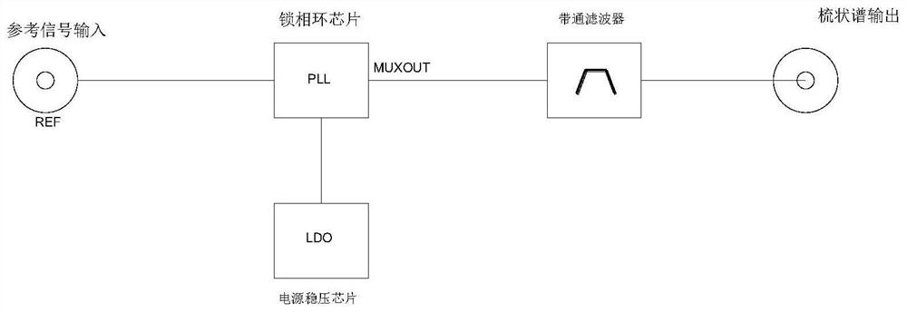
[0029] A high-flatness broadband comb spectrum generator based on a phase-locked loop mechanism, including an R frequency divider, a phase detector PD, a loop filter LP, a voltage-controlled oscillator VCO, an N frequency divider, and a bandpass filter, The R frequency divider, phase detector PD, loop filter LP, voltage controlled oscillator VCO, N frequency divider, and bandpass filter are connected in sequence, and the other end of the R frequency divider is the signal input end, and the bandpass filter The other end of the device is the signal output end, and the output end of the N frequency divider is connected with the input end of the phase detector PD.

[0030] The phase detector PD, R frequency divider, N frequency divider and voltage-controlled oscillator VCO are packaged in a phase-locked loop chip PLL.

[0031] A loop filter LP is also connected to the phase-locked loop chip PLL.

[0032] The phase-locked loop chip PLL is also connected with a linear regulator chi...

Embodiment 2

[0036] like Figure 5 As shown, a high-flatness broadband comb spectrum generator based on the phase-locked loop mechanism, the phase detector PD, R frequency divider, N frequency divider, voltage-controlled oscillator VCO and loop filter LP are composed of A phase-locked loop PLL is used, and the frequency of the high-frequency clock is locked by using the comb-shaped spectral spacing as the phase-detection frequency of the phase-locked loop. spectral signal.

[0037] The reference input signal input at the signal input end is input to the input end of the phase detector after being frequency-divided by the R frequency divider, and at the same time, the output of the voltage-controlled oscillator VCO is another input of the phase detector after being processed by the N frequency divider. When the phase-locked loop is stably locked to the high-frequency clock frequency, part of the output of the N frequency divider is extracted to obtain a comb spectrum signal, and then the i...


PUM


Abstract

The invention discloses a high-flatness broadband comb spectrum generator based on a phase-locked loop mechanism, which consists of an R frequency divider, a phase detector PD, a loop filter LP, a voltage-controlled oscillator VCO, and an N frequency divider , Band-pass filter, the reference signal input is divided by the R frequency divider into the phase detector input, the output of the R frequency divider is the comb spectrum interval frequency through program control, and the loop frequency fed back by the N frequency divider It is also set as the comb spectrum interval frequency. When the phase-locked loop is locked stably, part of the output of the N frequency divider is drawn out to obtain the comb spectrum signal, and then the unwanted signal outside the bandwidth is suppressed by the band-pass filter to obtain the final output. comb signal. Compared with traditional comb spectrum generators, this technology has the characteristics of high flatness, fine and adjustable spacing, wide band, and adjustable zero point of comb spectrum.

Description

technical field [0001] The invention relates to the field of comb spectrum generators, in particular to a high-flatness broadband comb spectrum generator based on a phase-locked loop mechanism. Background technique [0002] A comb spectrum generator is a modular component capable of generating comb spectrum signals, and is widely used in the field of modern communication systems. In multi-channel receivers, calibration sources are often used to calibrate the receiver to eliminate phase or amplitude errors between channels. If the conventional phase-locked loop method is used, only a single frequency point signal can be output each time and then scanned, but this will make the correction time very long, which affects the real-time requirements of the receiver. In order to shorten the calibration time and provide the real-time requirements of the receiver, it is very important to use a comb spectrum generator. In the application scenario of amplitude error calibration, it is...

Claims


Application Information

Patent Timeline
Patent Type & Authority Patents(China)
IPC IPC(8): H03K5/135H03L7/093H03L7/18
CPCH03K5/135H03L7/093H03L7/18
Inventor 石玉刘汉子尉旭波钟慧
Owner UNIV OF ELECTRONICS SCI & TECH OF CHINA
Why Eureka
Try Eureka