An anti-interference capacitive touch button controller and its realization method

A controller and capacitive technology, applied in the field of capacitive touch button controller, can solve the problems of high cost, poor anti-interference means, and wrong touch actions.

Active Publication Date: 2022-05-31
CHINA KEY SYST & INTEGRATED CIRCUIT
View PDF24 Cites 0 Cited by
  • Summary
  • Abstract
  • Description
  • Claims
  • Application Information

AI Technical Summary

Problems solved by technology

[0006] The purpose of the present invention is to provide an anti-interference capacitive touch button controller and its implementation method, so as to solve the problem that the wrong touch action is often caused by electromagnetic interference, and the existing anti-interference means are not effective and the cost is high

Method used


Image

  • An anti-interference capacitive touch button controller and its realization method
  • An anti-interference capacitive touch button controller and its realization method
  • An anti-interference capacitive touch button controller and its realization method

Examples


Embodiment 1

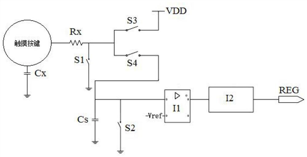
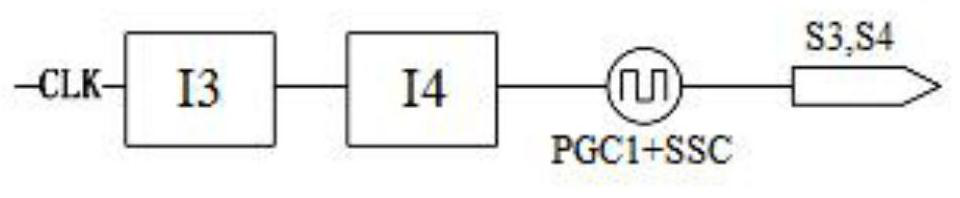
[0026] The invention provides an anti-interference capacitive touch key controller, the structure of which is as follows: figure 1 shown. The anti-interference capacitive touch key controller includes a touch key I0, an electrode capacitance Cx, a sampling capacitance Cs, an anti-static resistance Rx, an electronic component I1, a counter I2 and a register REG. Specifically, one end of the touch button I0 is grounded through the electrode capacitor Cx, and the other end is connected to one end of the anti-static resistor Rx; the other end of the anti-static resistor Rx is connected to the first reset switch S1 and the charging switch S3 respectively. , the charge transfer switch S4 is connected; the other end of the first reset switch S1 is grounded; the other end of the charging switch S3 is connected to the charging power supply VDD, the other end of the charge transfer switch S4 is connected to the sampling capacitor Cs, the second reset switch S2 and electronic component ...

Embodiment 2

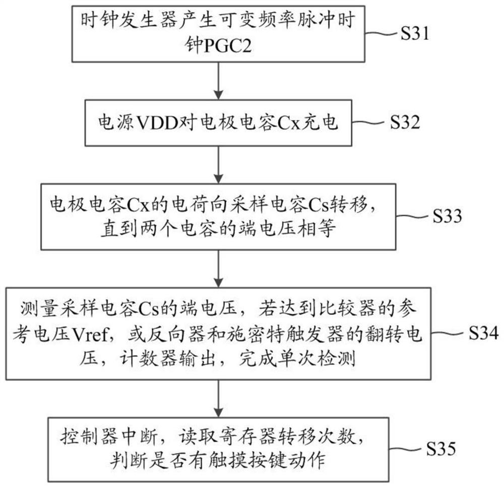
[0030] The present invention provides an implementation method of an anti-interference capacitive touch key controller. The schematic flowchart is as follows: figure 2 shown, including the following steps:

[0031] Step S31, the clock generator generates a variable frequency pulse clock PGC2;

[0032] Step S32, the power supply VDD charges the electrode capacitor Cx;

[0033] Step S33, the charge of the electrode capacitor Cx is transferred to the sampling capacitor Cs until the terminal voltages of the two capacitors are equal;

[0034] Step S34, measure the terminal voltage of the sampling capacitor Cs, if it reaches the reference voltage Vref of the comparator, or the inversion voltage of the inverter or Schmitt trigger, the counter outputs, and the single detection is completed;

[0035] Step S35, the controller interrupts, reads the transfer times of the register, and determines whether there is a touch button action.

[0036]Specifically, step 1: first, the anti-inte...


PUM


Abstract

The invention discloses an anti-interference capacitive touch button controller and a realization method, belonging to the technical field of touch sensing. The controller includes touch keys, electrode capacitors, sampling capacitors, antistatic resistors, electronic components, counters and registers. One end of the touch button is grounded through the electrode capacitance, and the other end is connected to the first reset switch, charging switch, and charge transfer switch through an antistatic resistor; the other end of the first reset switch is grounded; the other end of the charging switch is connected to the power supply VDD, and the charge transfer switch is connected to the other One end is connected to the sampling capacitor, the second reset switch and electronic components; the other end of the sampling capacitor and the second reset switch are both grounded, the electronic components are output to the counter, and the counter is connected to the register. Through the pulse clock with variable charge and discharge frequency, the spectrum energy during touch is evenly distributed within a certain range of frequencies, avoiding resonance with the energy peak of high-frequency interference signals, improving the robustness of charge migration acquisition and detection, and improving the anti-interference ability.

Description

technical field [0001] The invention relates to the technical field of touch sensing, in particular to an anti-interference capacitive touch key controller and an implementation method. Background technique [0002] In recent years, with the wide application of touch technology, capacitive touch for key applications has shown rapid growth. Capacitive touch keys not only appear in high-end products such as TVs, monitors, and smart homes, but have also penetrated into the field of consumer electronics. every aspect. [0003] Most of the touch key switches adopt the method of capacitance measurement. Specifically, the change of the capacitance value of the sensing point is judged by calculating the change of the electric charge on the capacitance at the sensing point, so as to obtain whether the touch action occurs. The document with the publication number CN101060321A discloses a touch sensing method. During specific implementation, the generation of a touch action is determi...

Claims


Application Information

Patent Timeline
Patent Type & Authority Patents(China)
IPC IPC(8): H03K17/96
CPCH03K17/962
Inventor 许卫明冯海英史兴强庄志伟朱晓宇
Owner CHINA KEY SYST & INTEGRATED CIRCUIT
Why Eureka
Try Eureka