Synthetic double-jet spray cooling device based on ultrasonic atomization

A technology of spray cooling and ultrasonic atomization, which is applied in the direction of cooling/ventilation/heating transformation, electrical components, electrical equipment structural components, etc. The effect of small droplet size

Active Publication Date: 2020-03-20
NAT UNIV OF DEFENSE TECH
View PDF6 Cites 0 Cited by
  • Summary
  • Abstract
  • Description
  • Claims
  • Application Information

AI Technical Summary

Problems solved by technology

The spray cooling device has compact structure, strong heat dissipation capacity, low energy consumption, and flexible control, and is expected to solve the heat dissipation and cooling problem of high heat flux density of miniaturized electronic devices

Method used


Image

  • Synthetic double-jet spray cooling device based on ultrasonic atomization
  • Synthetic double-jet spray cooling device based on ultrasonic atomization
  • Synthetic double-jet spray cooling device based on ultrasonic atomization

Examples


Embodiment 1

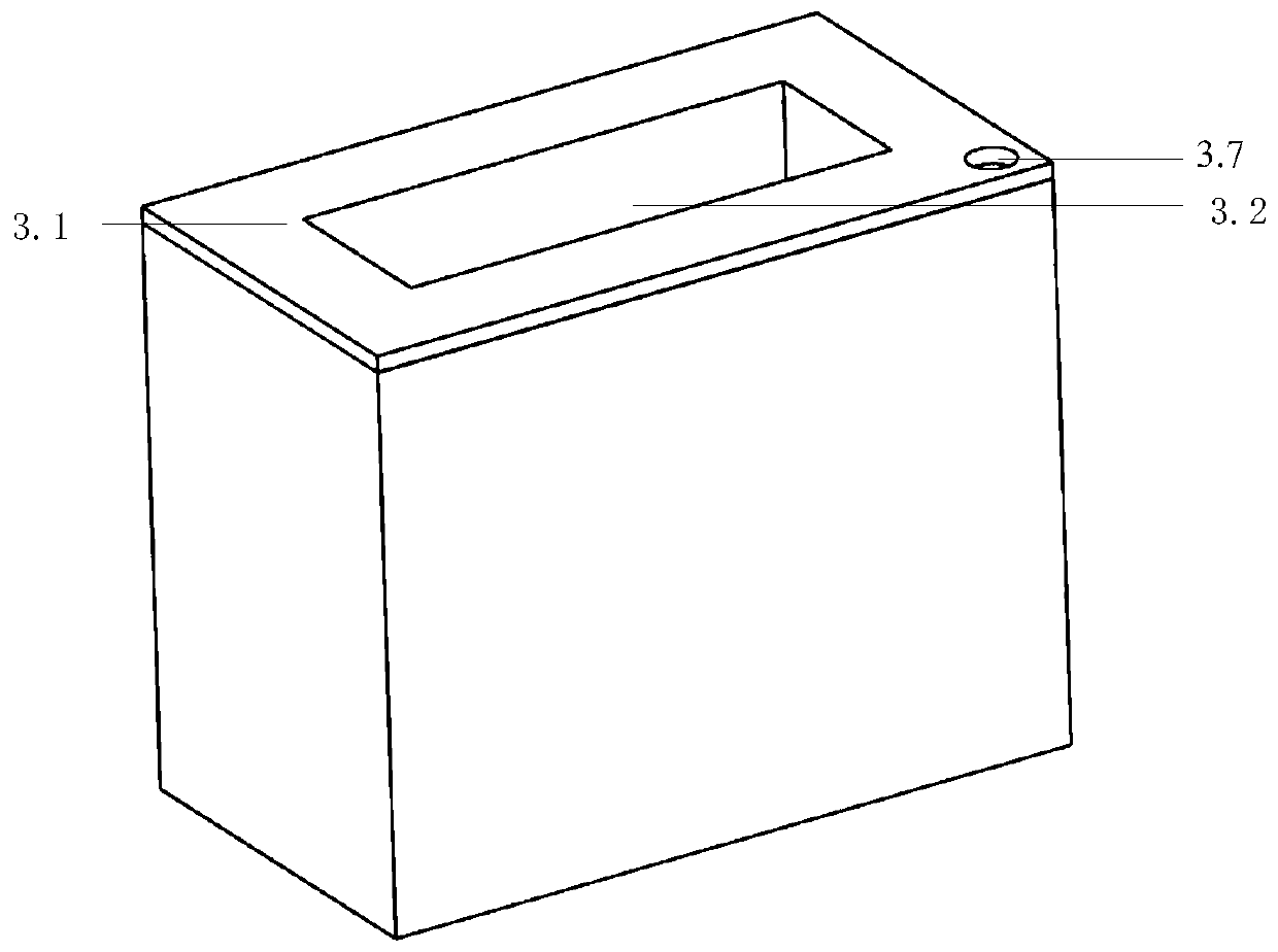
[0048] In Example 1: a synthetic dual-jet spray cooling device based on ultrasonic atomization includes a liquid supply device and a dual-jet actuator.

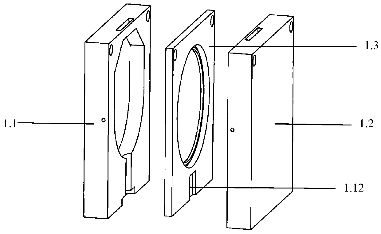
[0049] The double-jet actuator includes a left housing 1.1, a right housing 1.2 and a middle plate 1.3, the inside of the left housing 1.1 and the right housing 1.2 are provided with a concave cavity, and the middle part of the middle plate 1.3 is provided with a concave cavity. Through holes with the same cross section, a vibrating diaphragm 1.4 is arranged in the through hole, and the outer edge of the vibrating diaphragm 1.4 is sealed and connected to the inner wall of the through hole. As in this embodiment, the vibrating diaphragm 1.4 is fixedly installed by a rubber sealing ring Inside the through hole, this ensures a tight seal. The concave cavity inside the left housing 1.1 and the concave cavity inside the right housing 1.2 are respectively arranged on the left and right sides of the middle plate 1.3 and the left hou...

Embodiment 2

[0056] The ultrasonic atomization-based synthetic dual-jet spray cooling device provided in Example 2 also includes a liquid supply device and a dual-jet actuator.

[0057] The dual-jet actuator comprises a left housing 1.1, a right housing 1.2 and a middle plate 1.3. The inner sides of the left housing 1.1 and the right housing 1.2 are provided with concave cavities, and the middle part of the middle plate 1.3 is provided with a through hole with the same cross section as the concave cavity, and a vibrating diaphragm 1.4 is arranged in the through hole, and the vibrating diaphragm The outer edge of 1.4 is sealed and connected to the inner wall of the through hole. As in this embodiment, the vibrating diaphragm 1.4 is fixedly installed in the through hole through a rubber sealing ring, which can ensure the sealing. The concave cavity inside the left housing 1.1 and the concave cavity inside the right housing 1.2 are respectively arranged on the left and right sides of the midd...


PUM


Abstract

The invention belongs to the field of heat management and spray cooling, and provides a synthetic dual-jet spray cooling device based on ultrasonic atomization. On the basis of the double fluidic exciter which has its own vector control characteristic, A dual-jet actuator and an ultrasonic micro-hole atomizing sheet are combined, the cooling liquid is atomized by an atomizing sheet, and then the spray droplets are ejected by a synthetic double-jet module with the unique property of the synthetic double-jet. The spray speed, spray direction, spray pulse frequency of the spray cooling device ofthe invention can be adjusted by the driving frequency and amplitude of the double-jet exciter and other structural parameters. The spray cooling device is characterized in that Not only the droplet size is small, the atomization quantity is large, but also the spray speed is fast, the direction is adjustable, and the jet impingement cooling and the spray cooling have the advantages of strong heattransfer ability. The spray cooling device has the advantages of compact structure, strong heat dissipation ability, low energy consumption and flexible control, and is expected to solve the heat dissipation cooling problem of micro-miniaturized electronic devices with high heat flux density.

Description

technical field [0001] The invention belongs to the field of thermal management and spray cooling, in particular to a synthetic double-jet spray cooling device based on ultrasonic atomization. Background technique [0002] With the continuous improvement of electronic manufacturing technology and process level, the feature size of electronic devices and chips has been continuously reduced, the frequency has been continuously increased, and the integration level has been continuously increased, resulting in a substantial increase in the volume heat consumption density during operation, and the thermal failure of electronic components and The phenomenon of thermal degradation is becoming more and more prominent. Most of the existing mature heat transfer technologies are based on heat conduction and single convective heat transfer mechanisms, such as heat conduction, cold plates, heat sinks and fans. Traditional heat dissipation methods can no longer meet the needs of high-perfo...

Claims


Application Information

Patent Timeline
Patent Type & Authority Patents(China)
IPC IPC(8): H05K7/20
CPCH05K7/20345
Inventor 罗振兵何伟邓雄夏智勋赵朦
Owner NAT UNIV OF DEFENSE TECH
Why Eureka
Try Eureka