A Laser Scanning Method for Improving Interlaminar Strength and Reducing Warpage

A technology of laser scanning and laser scanning path, which is applied in the direction of improving energy efficiency, improving process efficiency, processing and manufacturing, etc., can solve the problems of interlayer strength difference, warpage and deformation, etc., to improve interlayer strength and reduce warpage The amount of deformation, the effect of enhanced interconnectivity

Active Publication Date: 2021-04-27
NANJING UNIV OF SCI & TECH
View PDF1 Cites 0 Cited by
  • Summary
  • Abstract
  • Description
  • Claims
  • Application Information

AI Technical Summary

Problems solved by technology

[0016] The present invention provides a laser scanning method for improving interlayer strength and reducing warping deformation, so as to overcome the defects of interlayer strength difference or warping deformation in the above-mentioned prior art

Method used


Image

  • A Laser Scanning Method for Improving Interlaminar Strength and Reducing Warpage
  • A Laser Scanning Method for Improving Interlaminar Strength and Reducing Warpage
  • A Laser Scanning Method for Improving Interlaminar Strength and Reducing Warpage

Examples


Embodiment 1

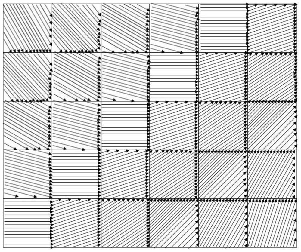
[0044] combine image 3 , a laser scanning method for improving interlayer strength and reducing warping deformation includes the following steps: Step 1: Divide a powder layer into 6*5 subsections (each small square in the figure is a subsection), using The first sub-section is scanned by laser in a unidirectional scanning manner, so that the first sub-section includes a plurality of laser scanning paths with a first angle (as shown by arrows in the sub-section in the figure), and each of the laser beams Each scanning path includes a start point and an end point; step 2: laser scanning is performed on a second sub-section adjacent to the first sub-section in a unidirectional scanning manner, so that the second sub-section includes multiple laser scanning paths with a second angle , each of the laser scanning paths includes a start point and an end point, wherein the second angle is different from the first angle; Step 3: use the scanning method of step 2 to scan the 3-30 sub-...

Embodiment 2

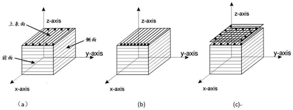
[0048] A laser scanning method for reducing warping deformation includes the following steps: Step 1: Laser scanning the first layer of powder in a unidirectional scanning manner, so that a layer of powder includes multiple laser scanning paths with a first angle, each Each of the laser scanning paths includes a starting point and an end point; Step 2: Laser scanning the second layer of powder in a unidirectional scanning manner, so that the second layer of powder includes a plurality of laser scanning paths with a second angle, each of the The laser scanning paths all include a start point and an end point, wherein the second angle is different from the first angle; Step 3: scan the remaining powder layers in turn, so that each layer of powder includes multiple laser scanning paths with a certain angle, each Each of the laser scanning paths includes a start point and an end point, wherein the angle of the laser scanning path of each layer of powder is different from the angle ...


PUM


Abstract

The present invention provides a laser scanning method for improving interlayer strength and reducing warping deformation. A powder layer is divided into multiple sub-sections, and each sub-section is scanned in turn, and the laser scanning path angle of each sub-section is compared with that of the adjacent Different, at the same time, the scanning path of at least a part of each sub-section is connected end to end with the scanning path of at least a part of the adjacent sub-section, and after scanning a powder layer, the next powder layer is scanned in the same way until all printing is completed, In this way, due to the continuous change of the scanning path, the thermal stress of adjacent sub-sections is different, so the amount of warping deformation is reduced as a whole, and at the same time, because the scanning path of at least a part of each sub-section is different from the scanning of at least a part of adjacent sub-sections Paths are connected end-to-end, thus enhancing interconnectivity between sub-sections and increasing interlayer strength.

Description

technical field [0001] The invention belongs to the technical field of additive manufacturing, and in particular relates to a laser scanning method for improving interlayer strength and reducing warping deformation. Background technique [0002] Additive Manufacturing (AM), commonly known as 3D printing, combines computer-aided design, material processing and forming technology, based on digital model files, and uses software and numerical control system to integrate special metal materials, non-metal materials and medical biomaterials , According to extrusion, sintering, melting, photo-curing, spraying and other ways to accumulate layer by layer, the manufacturing technology of manufacturing physical objects. Compared with the traditional processing mode of raw material removal-cutting and assembly, it is a "bottom-up" manufacturing method through material accumulation, starting from scratch. This makes it possible to manufacture complex structural parts that were restrict...

Claims


Application Information

Patent Timeline
Patent Type & Authority Patents(China)
IPC IPC(8): B22F3/105B33Y10/00B29C64/153
CPCB29C64/153B33Y10/00B22F10/00B22F10/28B22F10/366Y02P10/25
Inventor 阿森储勖阿西夫李仕博
Owner NANJING UNIV OF SCI & TECH
Why Eureka
Try Eureka