
Manufacturing method of wear-resistance part for concrete pump suitable for large-batch automation production

A technology of concrete pump and manufacturing method, which is applied to manufacturing tools, metal processing equipment, welding equipment, etc., can solve the problems of block collapse, hollowing out, and excessive welding seam gap.

Inactive Publication Date: 2018-12-21
HUNAN IND POLYTECHNIC +1
View PDF6 Cites 4 Cited by
  • Summary
  • Abstract
  • Description
  • Claims
  • Application Information

AI Technical Summary

Problems solved by technology

The main problem of this process is that after surfacing welding, the deformation of the cemented carbide mounting groove is large, resulting in uneven alloy gaps, and the brazing stress of the entire ring of cemented carbide is large. The problem of false welding on the bottom surface is prone to occur when flame brazing is used, and the weld gap is too large. Large, low welding strength, prone to collapse during use; followed by secondary heating of the surfacing wear-resistant layer, the hardness and wear resistance of the surfacing wear-resistant layer decreased significantly, resulting in early wear of the surfacing wear-resistant layer, The body is hollowed out, and the alloy ring is exposed and then brittle and broken due to impact.

Method used


Image

  • Manufacturing method of wear-resistance part for concrete pump suitable for large-batch automation production
  • Manufacturing method of wear-resistance part for concrete pump suitable for large-batch automation production
  • Manufacturing method of wear-resistance part for concrete pump suitable for large-batch automation production

Examples


Embodiment Construction

[0043] In order to enable those skilled in the art to better understand the technical solution of the present invention, the present invention will be described in further detail below in conjunction with the accompanying drawings and specific embodiments. And the features in the embodiments can be combined with each other.

[0044] The manufacturing method of the wear-resistant parts for concrete pumps suitable for large-scale automatic production provided by the present invention is illustrated by taking the wear-resistant parts as the production examples of wear-resistant rings and wear-resistant plates respectively.

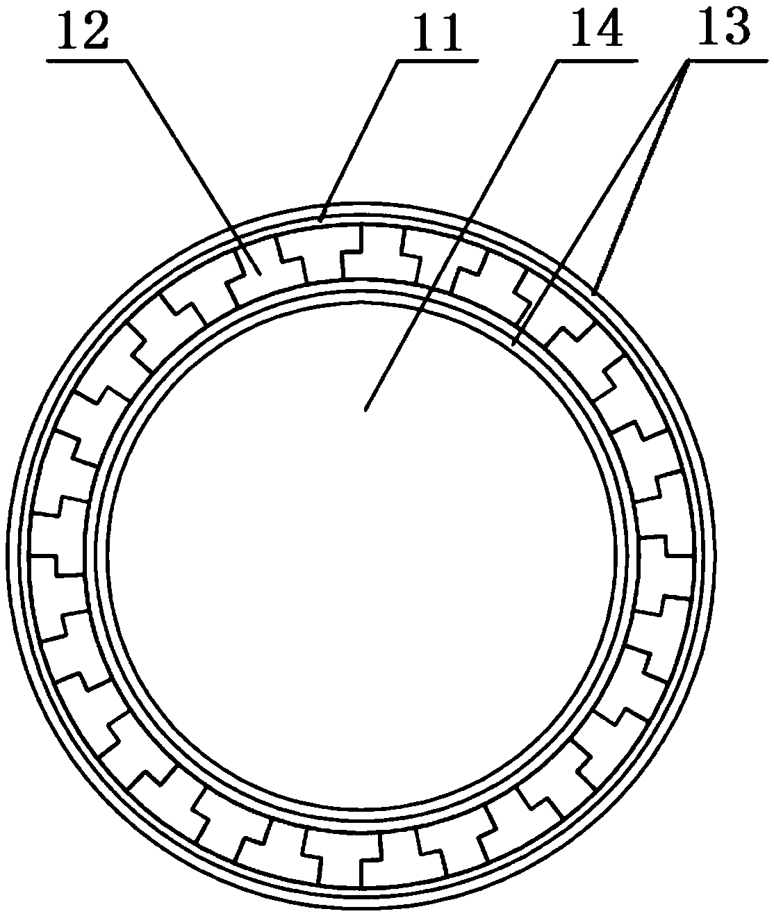
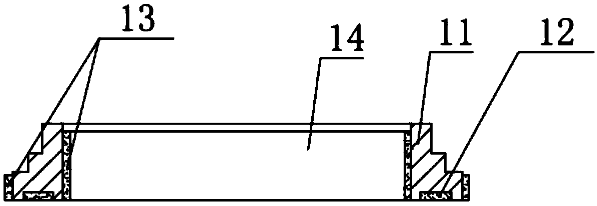
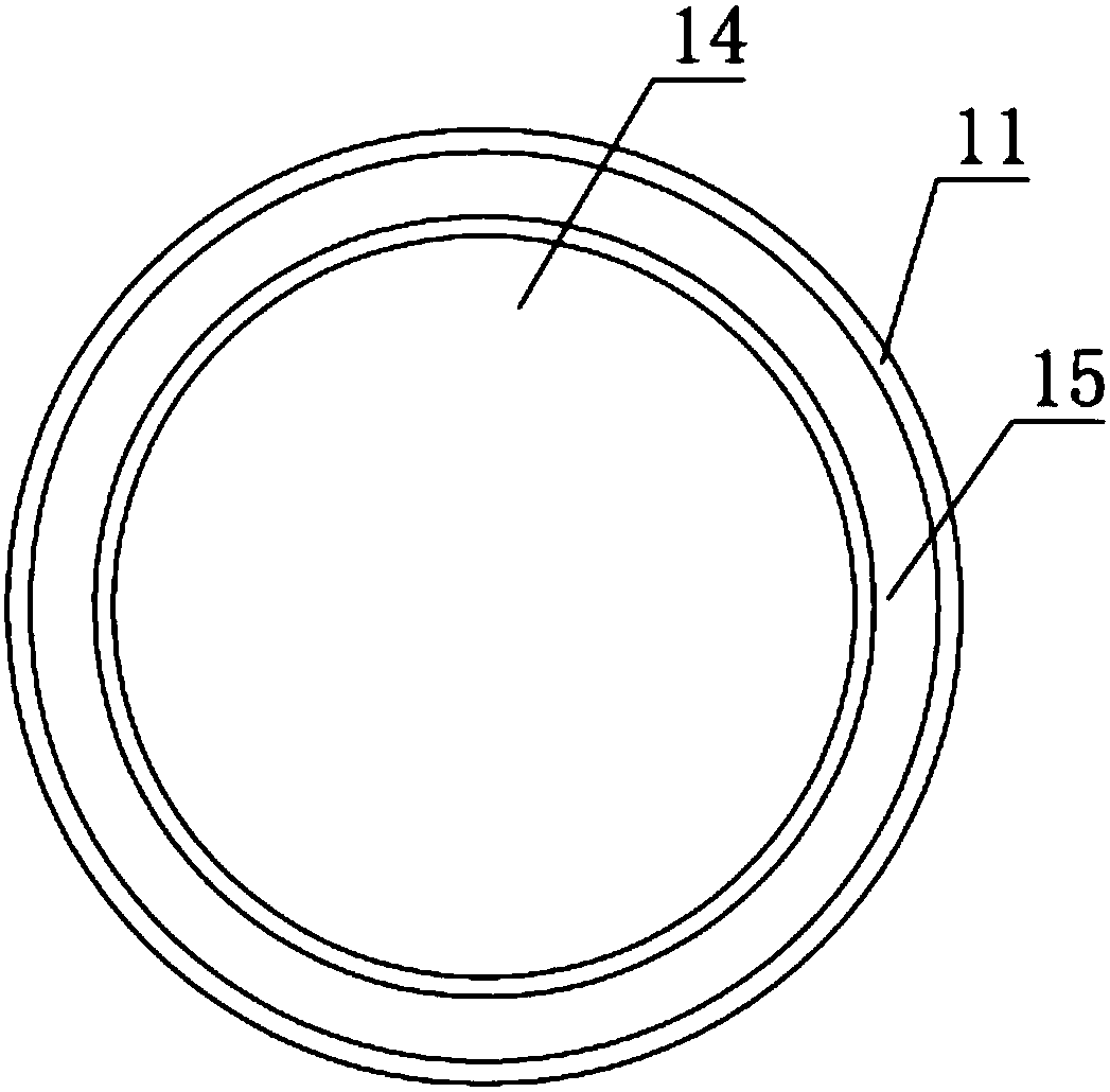
[0045] like Figure 1 to Figure 4 As shown, the wear-resistant ring includes a wear-resistant ring body 11, a hard alloy ring 12, and a surfacing wear-resistant layer 13. The wear-resistant ring body 11 is provided with a flow channel through hole 14, which is processed A cemented carbide mounting groove 15 is formed around the outside of one end of the flow...


PUM


Abstract

The invention discloses a manufacturing method of a wear-resistance part for a concrete pump suitable for large-batch automation production. The method comprises following steps that S1, a wear-resisting part body is manufactured, and a hard alloy block is prepared; S2, the wear-resisting part body and the hard alloy block are cleaned; S3, the hard alloy block is assembled in a hard alloy mountinggroove to be brazed and fixed; S4, after brazing, discharge annealing treatment is carried out; S5, an overlaying wear-resisting layer is formed on the wear-resisting part body; S6, annealing treatment is carried out after overlaying; S7, the surface of the hard alloy is subjected to grinding machining; and S8, subsequent finish machining and checkout are carried out. Continuous atmosphere protection brazing is adopted, oxidation of the wear-resisting part body and the hard alloy in the brazing process is avoided, overlaying after brazing is carried out, the problems that due to secondary heating of the overlaying wear-resisting layer, the structure property becomes bad, and the wear-resisting property is suddenly reduced are solved, the original structure and properties of an overlayinglayer are ensured, the protection effect of the overlaying wear-resisting layer on the body and the hard alloy is improved, product quality is improved, and the service life is prolonged.

Description

technical field [0001] The invention belongs to the technical field of a method for manufacturing a wear-resistant part of a concrete pump, and in particular relates to a method for manufacturing a wear-resistant part for a concrete pump suitable for mass automatic production. Background technique [0002] Wear-resistant plate and wear-resistant ring are the wear-resistant parts of the concrete pump, and they are also the key vulnerable parts of the concrete pump. The wear-resistant plate is also called the spectacle plate. It is installed on the back wall of the hopper. The holes communicate with the two conveying cylinders respectively; the wear-resistant ring is also called the cutting ring, which is installed on the S valve and has an opening. During the pumping operation, the S valve swings, and one opening of the wear ring communicates with the two openings of the wear plate alternately. During the pumping process, the wear-resistant plate and the wear-resistant ring ...

Claims


Application Information

Patent Timeline
IPC IPC(8): B23K1/008B23K1/20
CPCB23K1/008B23K1/206
Inventor 卢尚文杨志方龚艳丽简忠武孙忠刚
Owner HUNAN IND POLYTECHNIC
Learn More