H-shaped steel component polishing device

A steel component, I-shaped technology, applied in the direction of grinding drive device, grinding machine, grinding frame, etc., can solve the problems of time-consuming and labor-intensive, H-shaped steel components cannot be automatically polished, and achieve the effect of convenient grinding

Active Publication Date: 2018-12-21
JIANGSU YUEFA CONSTR ENG CO LTD
View PDF7 Cites 2 Cited by
  • Summary
  • Abstract
  • Description
  • Claims
  • Application Information

AI Technical Summary

Problems solved by technology

[0006] The purpose of the present invention is to provide a kind of H-shaped steel component grinding device, to solve the above-mentioned background technology, although the flange and the web of grindi

Method used


Image

  • H-shaped steel component polishing device
  • H-shaped steel component polishing device
  • H-shaped steel component polishing device

Examples


Embodiment 1

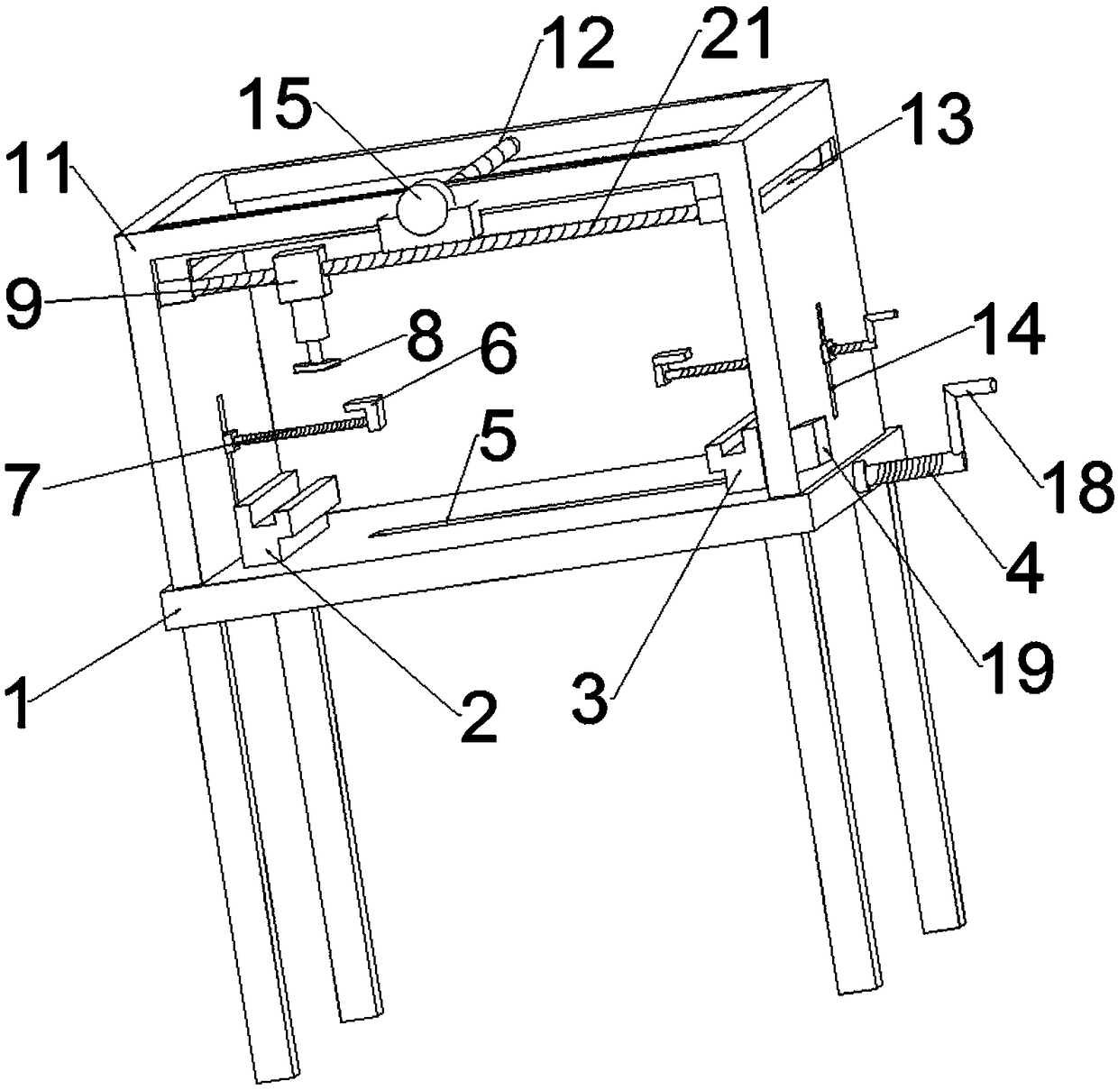
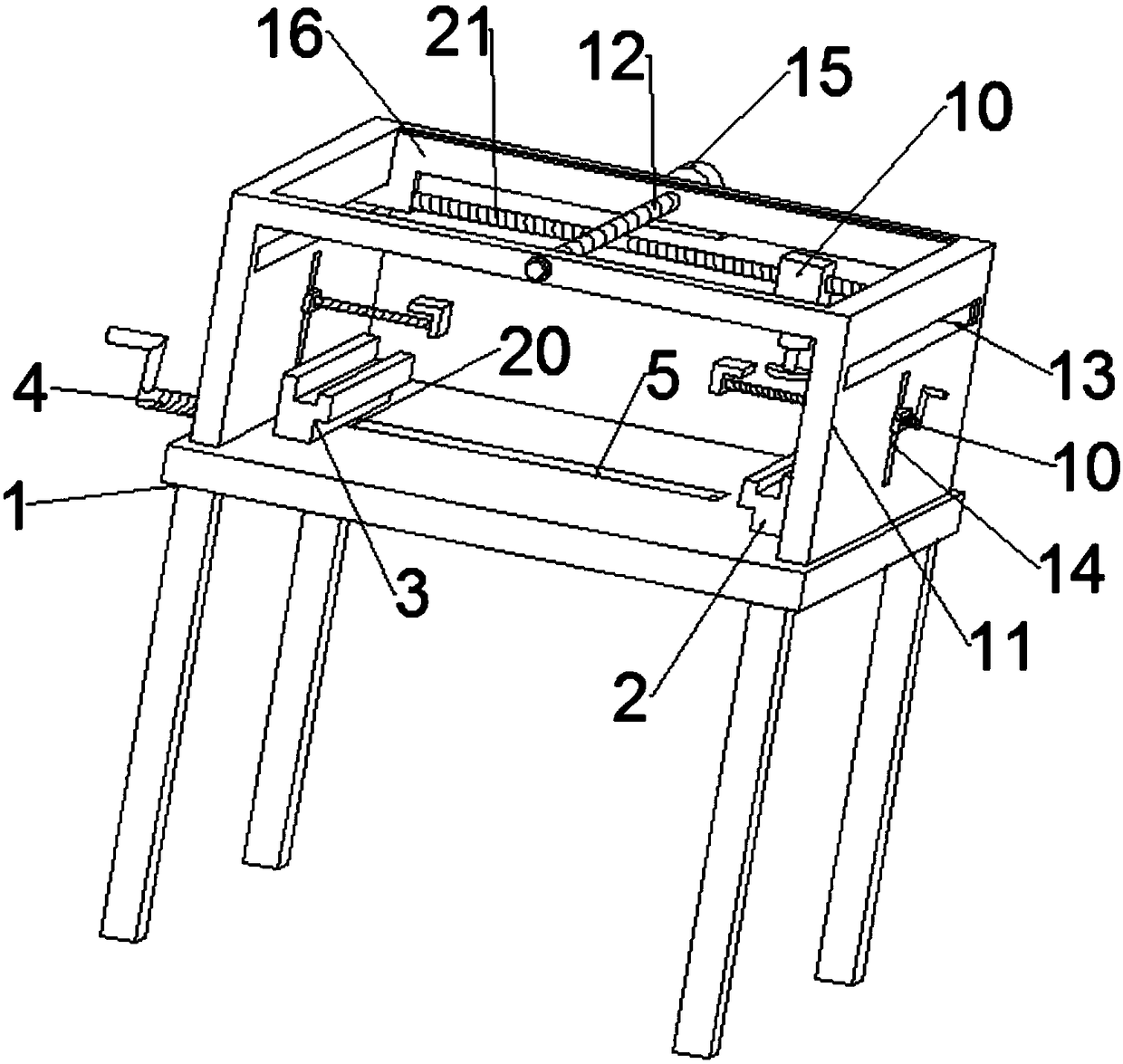
[0026] see Figure 1-4 , a H-shaped steel component grinding device, including a base plate 1, a fixed support block 2, a movable support block 3 and a PLC controller 19; the base plate 1 is provided with a transverse groove 5, and the base plate 1 is provided with a fixed support block 2 and a PLC controller 19; The movable support block 3 is fixedly connected with a slider 20 at the bottom of the movable support block 3, and the slider 20 is fixedly connected with a first screw mandrel 4, and the first screw mandrel 4 is rotatably connected with the bearings on the two side walls of the transverse groove 5. The top frame 11 is fixedly connected, and the top frame 11 is composed of side plates and horizontal plates. The middle ends of the two sets of horizontal plates of the top frame 11 are connected with a third screw rod 12 through bearing rotation, and one end of the third screw rod 12 runs through the top frame 11. The horizontal plate is fixedly connected with the outpu...

Embodiment 2

[0028] On the basis of Embodiment 1, the slider 20 is movably installed in the transverse groove 5 , which helps the first threaded rod 4 to drive the movable supporting block 3 to move. Both the fixed support block 2 and the movable support block 3 are provided with upward straight grooves and horizontal straight grooves; the fixed support block 2 and the movable support block 3 are all provided with upward straight grooves, so that the H-shaped steel member can Placed horizontally, the device can grind the web of the H-shaped steel member. Both the fixed support block 2 and the movable support block 3 are provided with straight grooves in the horizontal direction, which cooperate with the right-angled block so that the H-shaped steel member can be vertically Orientation, so that the device can grind the flange of the H-shaped steel member.

Embodiment 3

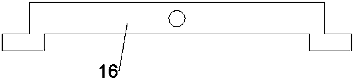
[0030] On the basis of Embodiment 1, the rotating motor 15 is fixedly mounted on the support plate connected to the outer wall of the top frame 11, so that the rotating motor 15 can conveniently drive the third screw mandrel 12 to rotate; 13 sliding connections help the slide bar 16 to drive the grinder 8 to move back and forth; one end of the second screw mandrel 7 and the first screw mandrel 4 is fixedly connected with a crank handle 18, which facilitates the movement of the movable support block 3 and the right-angle block 6, It is convenient to fix the H-shaped steel components; the outer wall of the I-shaped slider 10 is symmetrically fixed on the same horizontal line with clamping bolts 17, which is convenient for fixing the height of the right-angle block 6, so that the device is suitable for fixing H-shaped steel components of different heights; please refer to Figure 5 , the PLC controller 19 is electrically connected to the external power supply, and the PLC control...


PUM


Abstract

The invention discloses an H-shaped steel component polishing device and belongs to the technical field of steel structure polishing equipment. The H-shaped steel component polishing device comprisesa bottom plate; the bottom plate is provided with a transverse groove, a fixed supporting block and a movable supporting block; a sliding block is connected to the bottom of the movable supporting block; a first screw rod is connected to the sliding block; a top frame is connected to the bottom plate and comprises side plates and transverse plates; a third screw rod is connected to the middle endsof the two groups of the transverse plates of the top frame, is connected with the output end of a rotation motor and is rotationally connected with a bearing which is fixedly connected with the middle end of a sliding rod; a fourth screw rod is fixedly connected to the bottom of the sliding rod; a linear motor is fixedly connected to the fourth screw rod; a polishing machine is fixedly connectedto the bottom of the linear motor through an electric telescopic rod; an I-shaped sliding block is connected to a second straight groove in a sliding manner; and a second screw rod is fixedly connected to the I-shaped sliding block through a bearing. The H-shaped steel component polishing device provided by the invention is reasonable in design and high in automation degree in polishing of the surface of an H-shaped steel component.

Description

technical field [0001] The invention relates to the technical field of steel structure grinding equipment, in particular to an H-shaped steel component grinding device. Background technique [0002] H-shaped steel is an economical cross-section high-efficiency profile with more optimized cross-sectional area distribution and a more reasonable strength-to-weight ratio. It is named because its cross-section is the same as the English letter "H". Since all parts of the H-shaped steel are arranged at right angles, the H-shaped steel has the advantages of strong bending resistance in all directions, simple construction, cost saving and light structural weight, and has been widely used. [0003] During the production and processing of the H-shaped frame, since there is rust on the surface of the frame, the frame plate needs to be polished before welding to remove the rust. But present derusting device also has some problems. [0004] For example, Chinese patent application numbe...

Claims


Application Information

Patent Timeline
IPC IPC(8): B24B27/00B24B41/02B24B41/06B24B19/00B24B47/08
CPCB24B19/004B24B27/0015B24B41/02B24B41/06B24B47/08
Inventor 吉杰蒋红伟徐霞卞红军
Owner JIANGSU YUEFA CONSTR ENG CO LTD
Why Eureka
Try Eureka