Hat rudder and ship
A cap plate and rudder shaft technology, which is applied in the direction of rudder steering and steering, can solve the problems of high material requirements, large rudder resistance, large size, etc., achieve huge economic benefits, reduce strength requirements, and increase the speed of the ship
- Summary
- Abstract
- Description
- Claims
- Application Information
AI Technical Summary
Problems solved by technology
Method used
Image
Examples
no. 1 example
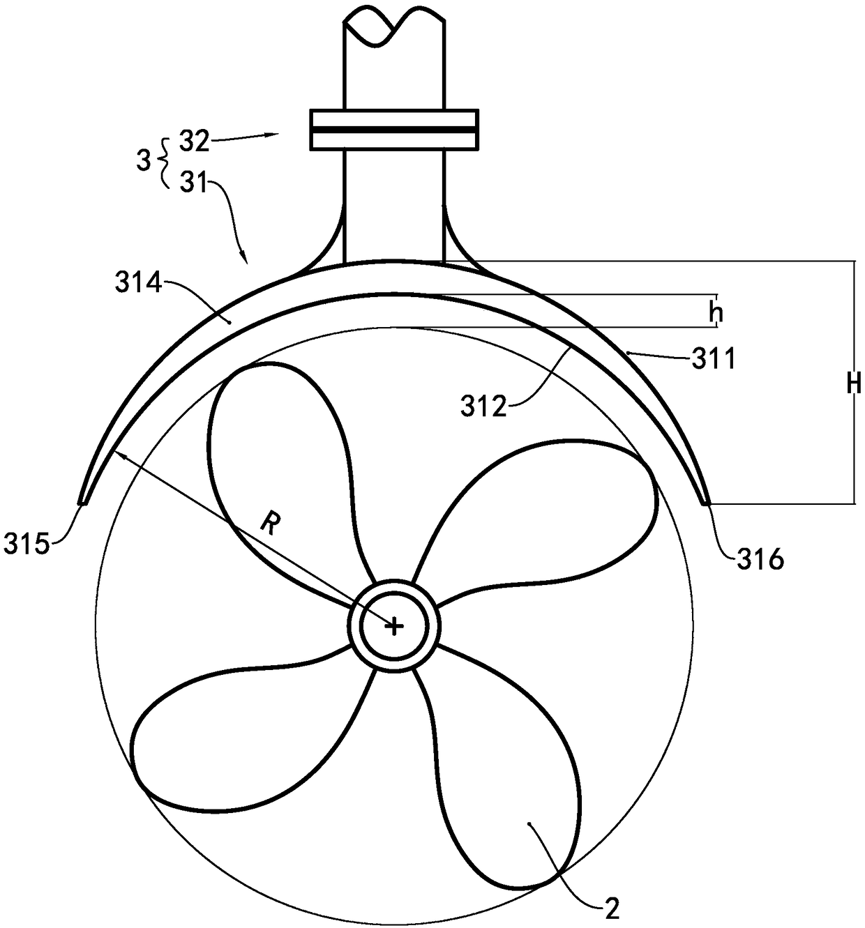
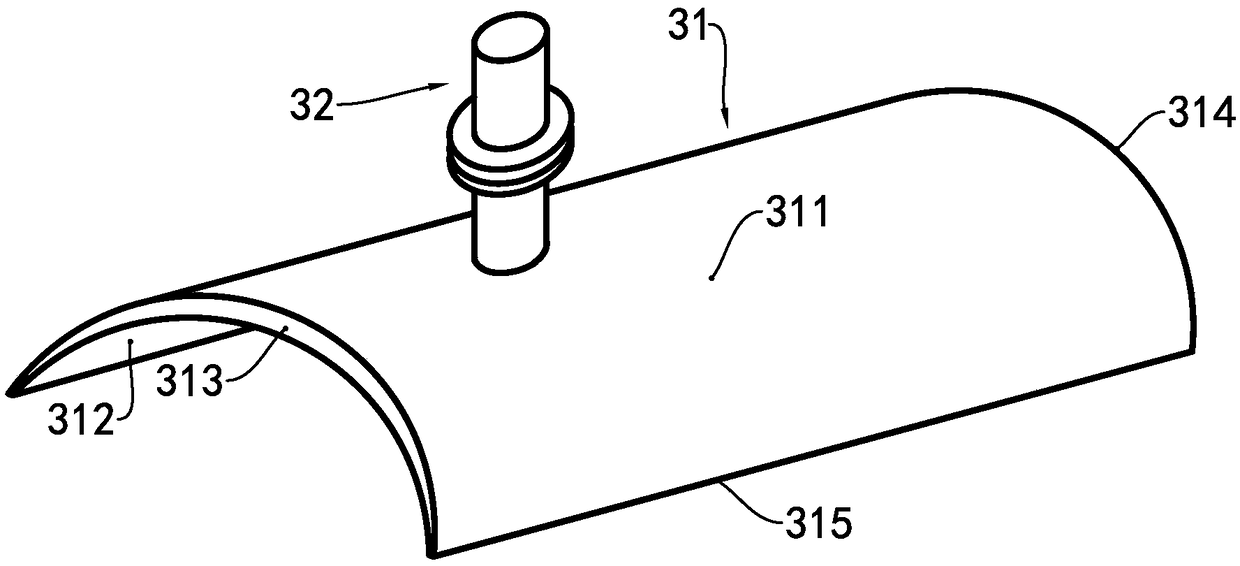
[0042] see image 3 The cap rudder of this example is only made of cap plate 31 and rudder shaft 32, and cap plate 31 has top surface 311, bottom surface 312, front end surface 313, rear end surface 314, left end surface 315 and right end surface 316. It can be understood that each end surface referred to in the present invention can be a plane or an arc surface, and should be selected comprehensively considering the fluid resistance and the simplification of the process. In this example, the bottom surface 312 is a cylindrical surface formed by a section of circular arc stretched longitudinally. The radius of the cylindrical surface circle is equal to the radius of the paddle that the hat rudder is adapted to plus a value of h, and the value of h can range from 0.1%d to The value between 100%d, where d is the diameter of the propeller, and the main considerations for the value of h are ship type and design speed, which can be determined through model experiments during implem...
no. 2 example
[0044] see Figure 4 The difference between this example and the first embodiment of the hat rudder is that the rib 33 is added, and the rib 33 is composed of a first rib 331 and a second rib 332 . The first rib plate 331 is vertically installed on the top surface 311, and one end thereof is connected to the rudder shaft 31, and the other end extends to the front end surface 313; the second rib plate 332 is vertically installed on the top surface 311, and one end thereof is connected to the rudder shaft 31 , and the other end extends to the rear end surface 314 . On the one hand, the ribs 33 can provide the effective area of the rudder plate, and on the other hand, can provide the strength for fixing the hat plate 31 .
[0045] see Figure 5 In this example, when steering, the rudder area that can produce the rudder effect is equal to twice the longitudinal projected area of the hat plate 31 plus the area of the first rib 331 and the second rib 332 .
no. 3 example
[0047] It can be understood that, according to the present invention, the curvature of the cap plate in the transverse direction can be zero, see Figure 6 and Figure 7, the feature of the hat rudder in this example is that the vertical and horizontal curvature of the hat plate 31 is zero, and it is a flat plate. In this example, when the rudder is steered, the rudder area that can produce rudder effect is the first rib 331 and the second rib 332, and The rudder effect produced by the cap plate 31 can be ignored. The main function of the cap plate 31 is rectification, that is, in the longitudinal view, the water flow in front of and behind the propeller is regularized by the cap plate 31 to improve the propulsion efficiency. The other function is the same as the previous two examples Similarly, the anti-rolling moment is provided when the ship rolls longitudinally.
PUM
 Abstract
Description
Claims
Application Information
 - R&D
- Intellectual Property
- Life Sciences
- Materials
- Tech Scout
- Unparalleled Data Quality
- Higher Quality Content
- 60% Fewer Hallucinations
Browse by: Latest US Patents, China's latest patents, Technical Efficacy Thesaurus, Application Domain, Technology Topic, Popular Technical Reports.
© 2025 PatSnap. All rights reserved.Legal|Privacy policy|Modern Slavery Act Transparency Statement|Sitemap|About US| Contact US: help@patsnap.com


