Self-resetting column foot node based on shape memory alloy bar and steel structure building

A memory alloy, column foot joint technology, applied in the direction of buildings, building types, building components, etc., can solve the problems of difficult alignment during hoisting, difficult to withstand lateral force, difficult to control the size of prestress, and achieve energy consumption and The effect of good self-resetting ability and good bearing capacity

Active Publication Date: 2018-12-21
SHANDONG UNIV
View PDF8 Cites 33 Cited by
  • Summary
  • Abstract
  • Description
  • Claims
  • Application Information

AI Technical Summary

Problems solved by technology

[0006] In the patent of authorized notification number CN206091073U, an externally tensioned energy-dissipating self-resetting rectangular steel pipe concrete frame column foot node is disclosed. This column foot node provides restoring force through prestressed tendons, and then through the surrounding buckling-resistant steel plates Energy consumption, so the structure is complex, and at the same time, the tension of the prestressed tendons is difficult to control the size of the prestressed tendons. At the same time, the prestressed tendons will also relax. When the pillar shakes, it is easy to bend and deform.
[0007] In the patent of authorized notification number CN 207063676 U, a swinging column base is disclosed. The advantage of this column base is that it can adapt to the requirements of different inclination angles. The disadvantage is that when the earthquake ends, it can only be restored by gravity, and there is no other Foreign objects provide restoring force, it is difficult to return to the original position, and it is difficult to center when hoisting
[0008] In the patent authorized public number CN 207296559 U, a self-resetting column base is disclosed. The advantage of this column base is that the superelastic memory alloy rods on both sides can provide tension recovery on both sides, but the column base lacks shear resistance. key, it is difficult to withstand lateral force, and at the same time, the superelastic memory alloy rods on both sides are easy to buckle, damage and destroy when they are under pressure

Method used


Image

  • Self-resetting column foot node based on shape memory alloy bar and steel structure building
  • Self-resetting column foot node based on shape memory alloy bar and steel structure building
  • Self-resetting column foot node based on shape memory alloy bar and steel structure building

Examples


Embodiment Construction

[0040] It should be pointed out that the following detailed description is exemplary and intended to provide further explanation to the present application. Unless defined otherwise, all technical and scientific terms used herein have the same meaning as commonly understood by one of ordinary skill in the art to which this application belongs.

[0041] It should be noted that the terminology used here is only for describing specific implementations, and is not intended to limit the exemplary implementations according to the present application. As used herein, unless the context clearly dictates otherwise, the singular is intended to include the plural, and it should also be understood that when the terms "comprising" and / or "comprising" are used in this specification, they mean There are features, steps, operations, means, components and / or combinations thereof.

[0042] As introduced in the background technology, in the prior art, there are deficiencies in the existing tech...


PUM


Abstract

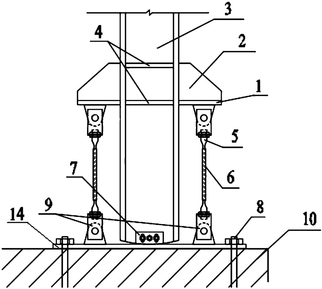
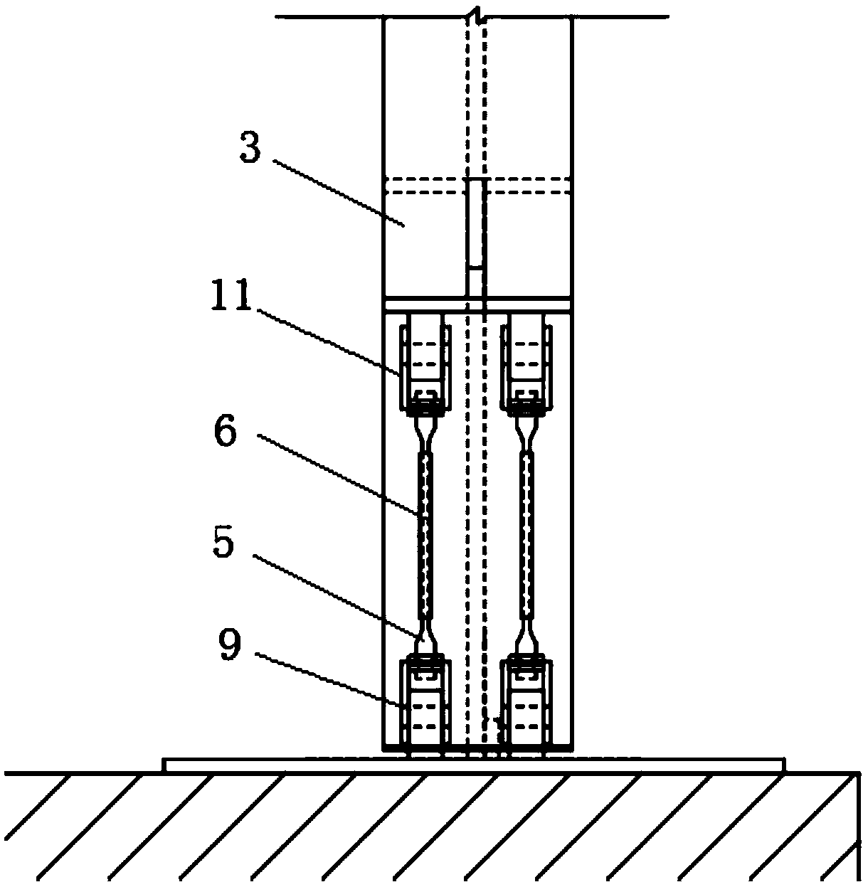
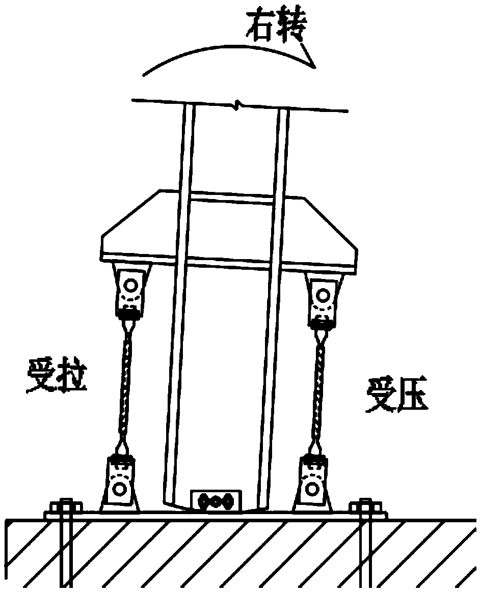
The invention discloses a self-resetting column foot node based on a shape memory alloy bar and a steel structure building. The self-resetting column foot node solves the problems in the prior art ofhigh rigidity after the nominal yield of the node and easy loss of initial rigidity after an earthquake occurs, and has the advantages of good energy consumption performance and self-resetting capability under the action of earthquake load, after suffering from an excessive deformation or at low temperature, the initial rigidity is not lost, and the structural steel column and the column foot nodeare not damaged; according to the technical scheme, the self-resetting column foot node and the steel structure building comprises a concrete foundation, a bottom plate is fixed on the upper part ofthe concrete foundation, the bottom plate is connected with a vertical supporting column through an anti-shear connecting plate, the two sides of the support column are symmetrically provided with ananchor plate, the anchor plate and the bottom plate are connected with a shape memory alloy rod through a hinged support, the shape memory alloy rod provides an energy consumption performance and a self-resetting performance for the nodes while providing rotational rigidity; the circumference of the shape memory alloy rod is coated with a sleeve, and the sleeve can restrain the buckling of the shape memory alloy rod under compression so as to improve the ductility and bearing capacity of the shape memory alloy rod when the shape memory alloy rod is pressed.

Description

technical field [0001] The invention relates to the field of building steel structures, in particular to a self-resetting column base node based on a shape memory alloy bar and a steel structure building. Background technique [0002] The column foot is mainly used to fix the steel structure column on the foundation, and at the same time release the force borne by the column to the foundation while supporting the column. Column feet can be divided into hinged column feet and rigidly connected column feet. The former can only transmit shear force and axial force, while the latter can transmit shear force, axial force and bending moment. Therefore, the rigidly connected column foot will bear a large bending moment at the bottom while being subjected to lateral force, which will have a greater impact on the column bottom. The hinged column foot mainly bears shear force and axial force, and at the same time releases the bending moment through rotation. [0003] In recent years...

Claims


Application Information

Patent Timeline
Patent Type & Authority Applications(China)
IPC IPC(8): E04B1/24E04B1/98E04H9/02
CPCE04B1/2403E04B2001/2463E04H9/024
Inventor 邱灿星齐健张邑尘陈城
Owner SHANDONG UNIV
Why Eureka
Try Eureka