Vertical type sintering furnace with movable furnace bottom

A sintering furnace and movable technology, applied in the field of heating furnaces, can solve the problems of uneven shrinkage, high heating temperature, material cracking, etc., and achieve the effects of avoiding radiation shadow effects, improving temperature uniformity, and saving energy costs.

Active Publication Date: 2018-12-21
东莞市旺安节能科技设备有限公司
View PDF8 Cites 7 Cited by
  • Summary
  • Abstract
  • Description
  • Claims
  • Application Information

AI Technical Summary

Problems solved by technology

[0003] At present, the sintering furnace adopts the principle of heat radiation to conduct heat to the sintered product. When there are many furnace materials being heated, there will be a shadow effect. Generally speaking, the temperature of the sintered product that is not directly radiated will be much lower than that of the product that is directly radiated. The part of the radiation causes the uneven temperature field, so that the temperature of the sintered product itself is uneven, which is also easy to cause the sintered product to shrink unevenly and form internal stress, thereby causing material cracking and affecting the practical performance of the sintered product In addition, due to the shadow effect, the sintered product needs to be fully heated, which requires a long processing time, resulting in a large energy consumption; the heating temperature of the sintering furnace is high, and the operator needs to be close to the furnace operation, there are potential safety hazards such as heatstroke and burns for operators

Method used


Image

  • Vertical type sintering furnace with movable furnace bottom
  • Vertical type sintering furnace with movable furnace bottom
  • Vertical type sintering furnace with movable furnace bottom

Examples


Embodiment Construction

[0026] In order to make the object, technical solution and technical effect of the present invention clearer, the present invention will be further described below in conjunction with specific embodiments. It should be understood that the specific embodiments described here are only used to explain the present invention, not to limit the present invention.

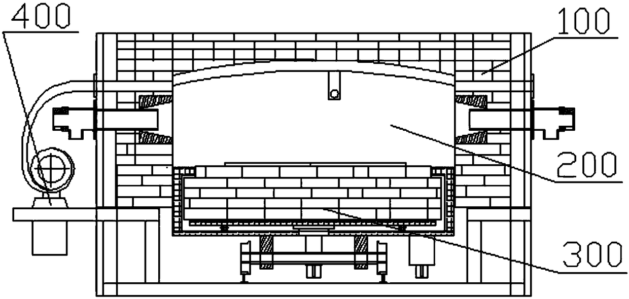
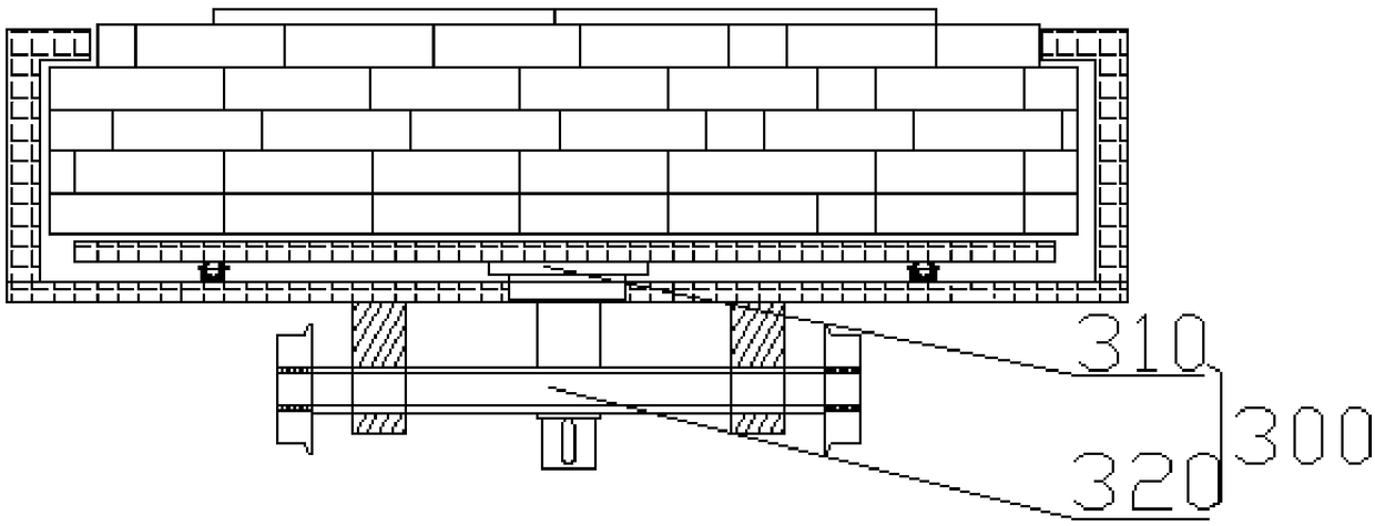
[0027] refer to figure 1 and figure 2 As shown, a vertical sintering furnace with a movable furnace bottom includes a furnace body 100, at least one heating nozzle 111 disposed on the side wall of the furnace body 1, a furnace chamber 200 disposed within the furnace body, and a furnace body disposed at the bottom of the furnace chamber. Furnace bottom 300; in this embodiment, a rotating mechanism 310 and a moving mechanism 320 connected thereto are provided below the furnace bottom 300, and the rotating mechanism 310 can drive the furnace bottom 300 to be adjustable in the furnace 200 The moving mechanism 320 supports t...


PUM


Abstract

The invention provides a vertical type sintering furnace with a movable furnace bottom. The vertical type sintering furnace comprises a furnace body, at least one heating nozzle arranged on the side wall of the furnace body, a hearth arranged in the furnace body and the furnace bottom arranged at the bottom of the hearth; a rotating mechanism connected with the furnace bottom and a moving mechanism are arranged under the furnace bottom, the rotating mechanism can drive the furnace bottom to perform speed-adjustable rotating motion in the hearth, the moving mechanism supports the rotating mechanism and can drive the rotating mechanism to perform linear movement; and the vertical type sintering furnace further comprises a temperature control device, wherein the temperature control device comprises a temperature sensor, a fan and a PLC control cabinet, the temperature sensor is arranged in the hearth, and the fan and the PLC control cabinet are arranged outside the furnace body. By adopting the rotating mechanism, a radiation shadow effect is effectively avoided, so that the temperature uniformity of sintered products is improved, and material cracking caused by uneven heating can beavoided; by adopting the moving mechanism, potential safety hazards such as heatstroke and scalding possibly caused during the near-furnace operation can be avoided; and by adopting the temperature control device, accurate control over the temperature of the hearth is realized.

Description

technical field [0001] The invention relates to the technical field of heating furnaces, in particular to a vertical sintering furnace with a movable furnace bottom. Background technique [0002] With the development of science and technology, the performance requirements of materials in the defense industry and science and technology fields are getting higher and higher. Various industrial electric furnaces are widely used in the development and production of new materials, and high-temperature sintering furnaces are one of the most widely used. It can meet the needs of the fields of semiconductor, metallurgy, electronics, machinery, chemical industry and hard alloy materials. Sintering is the main process after powder metallurgy materials are pressed and formed into finished products; the essence of sintering is to heat the pressed and formed powder blanks in a vacuum state, and to bond the powder products together through a series of physical and chemical changes. , the ...

Claims


Application Information

Patent Timeline
Patent Type & Authority Applications(China)
IPC IPC(8): F27B13/00F27B13/10F27B13/12F27B13/14
CPCF27B13/00F27B13/10F27B13/12F27B13/14
Inventor 熊仲民
Owner 东莞市旺安节能科技设备有限公司
Why Eureka
Try Eureka