Ultrashort pulse time width measurement device and method based on spectral interference

An ultra-short pulse, time width technology, applied in the direction of instruments, etc., can solve the problems of only a dozen picoseconds, difficult measurement, small measurement time width, etc., to achieve good applicability, sensitive measurement, and high measurement sensitivity. Effect

Active Publication Date: 2018-12-21
TIANJIN UNIV
View PDF10 Cites 8 Cited by
  • Summary
  • Abstract
  • Description
  • Claims
  • Application Information

AI Technical Summary

Problems solved by technology

At present, the measurement of optical signals mainly uses photodetectors and oscilloscopes to observe the changes in the signal amplitude. However, the fastest response time of photodetectors can only reach a dozen picoseconds, which is far from satisfying the requirements for femtoseconds. Requirements for time width measurements of pulses and even attosecond pulses
The traditional optical autocorrelation method and frequency-resolved optical gate method can satisfy the measurement of femtosecond pulse time width, but the measurement time width range is small, generally tens of femtoseconds to more than ten picoseconds, when the pulse When the width is as narrow as several femtoseconds or even attoseconds, it is difficult to measure, and because it is based on the optical frequency doubling effect to measure the frequency doubled signal of the ultrashort pulse to be measured, it is required that the incident ultrashort pulse energy should be greater than times Therefore, it is not applicable to ultrashort pulses with low energy in some special cases (such as ultrashort pulses directly generated by fiber laser resonators)

Method used


Image

  • Ultrashort pulse time width measurement device and method based on spectral interference
  • Ultrashort pulse time width measurement device and method based on spectral interference
  • Ultrashort pulse time width measurement device and method based on spectral interference

Examples


Embodiment Construction

[0021] The specific implementation manners of the present invention will be further described in detail below in conjunction with the accompanying drawings.

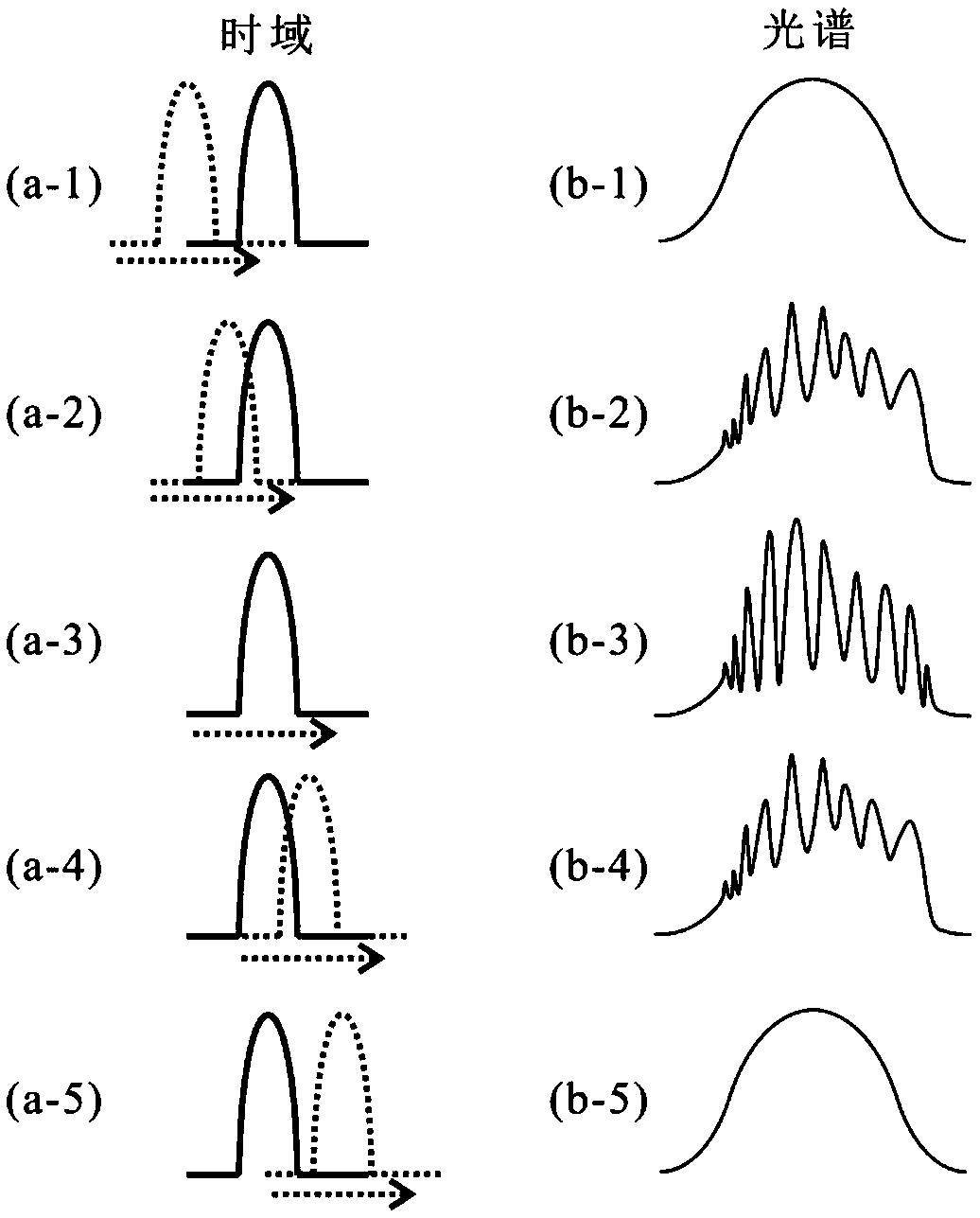
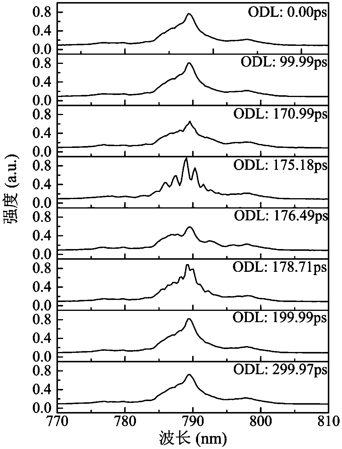
[0022] The device and method for measuring ultrashort pulse time width based on spectral interference of the present invention uses the principle of ultrashort pulse transmission transformation limit to convert the measurement of ultrashort pulse time width into the measurement of spectral interference oscillation intensity. The degree of spectral interference oscillation is converted into the distance of space movement, so as to realize the precise measurement of the time width of the ultrashort pulse to be measured.

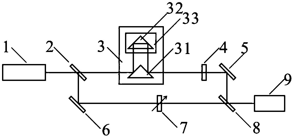
[0023] The invention proposes a device for measuring ultrashort pulse time width based on spectral interference. The device mainly includes an ultrashort pulse laser to be tested, a measuring optical path, a reference optical path, a beam combiner, and a spectrum analyzer.

[0024] The ultrashort pulse of...


PUM


Abstract

The invention discloses an ultrashort pulse time width measurement device and method based on spectral interference. The device comprises a to-be-measured ultrashort pulse laser, a 50:50 beam splitter, a measurement optical path, a reference optical path, a beam combiner and a spectral analyzer. According to the method, a to-be-measured ultrashort pulse is divided into two to-be-measured ultrashort pulse beams with equal power; the to-be-measured ultrashort pulse beams are emitted to the beam combiner through the measurement optical path, time delay of the to-be-measured ultrashort pulse in the measurement optical path is regulated, and the polarization state of the to-be-measured ultrashort pulse in the measurement optical path is regulated to be matched with a to-be-measured ultrashort pulse in the reference optical path; the optical power of the to-be-measured ultrashort pulse in the reference optical path is regulated to be equal to the optical power of the to-be-measured ultrashort pulse output by the measurement optical path; and the change of the spectral interference oscillation degree of the to-be-measured ultrashort pulse is measured, and the time width of the to-be-measured ultrashort pulse is calculated. Through the ultrashort pulse time width measurement device and method, the mode of measuring frequency-doubled signal intensity of the to-be-measured ultrashort pulse based on a frequency doubling crystal in traditional ultrashort pulse time width measurement is abandoned, measurement sensitivity is high, and meanwhile good applicability is achieved.

Description

technical field [0001] The invention relates to the fields of ultrashort pulse spectrum measurement and time width measurement, in particular to an ultrashort pulse time width measurement device and method based on spectral interference. Background technique [0002] Compared with continuous laser, ultrashort pulse has the advantages of high peak power, large single pulse energy, and low average power. Therefore, since its birth, it has been moving towards shorter pulse width, higher energy density, and faster range of wavelengths. The direction of tuning is developing. The appearance of ultrashort pulses provides a new way for human beings to study ultrafast optical phenomena and high-order nonlinear optical phenomena. Its application fields are expanding day by day. It has been widely used in chemistry, life science and other fields. Due to its fast and high resolution characteristics, a variety of time-resolved spectroscopy techniques and pump-detection techniques have be...

Claims


Application Information

Patent Timeline
Patent Type & Authority Applications(China)
IPC IPC(8): G01J11/00
CPCG01J11/00
Inventor 江俊峰刘铁根张永宁王双刘琨张学智马喆顾高菲
Owner TIANJIN UNIV
Why Eureka
Try Eureka