Planar array type shear force touch sensor and shear force parameter detection method

A tactile sensor and plane array technology, applied in the field of plane array shear force tactile sensor and shear force parameter detection, can solve the problem of inability to judge the size and action position of shear force, complex sensor structure design, insufficient practical applicability, etc. problem, to achieve the effect of easy promotion, simple structure and long service life

Pending Publication Date: 2018-12-21
HEBEI UNIV OF TECH
View PDF1 Cites 1 Cited by
  • Summary
  • Abstract
  • Description
  • Claims
  • Application Information

AI Technical Summary

Problems solved by technology

The sensor can only detect the direction of the shear force, but cannot judge the magnitude and action position of the shear force, an

Method used


Image

  • Planar array type shear force touch sensor and shear force parameter detection method
  • Planar array type shear force touch sensor and shear force parameter detection method
  • Planar array type shear force touch sensor and shear force parameter detection method

Examples


Embodiment 1

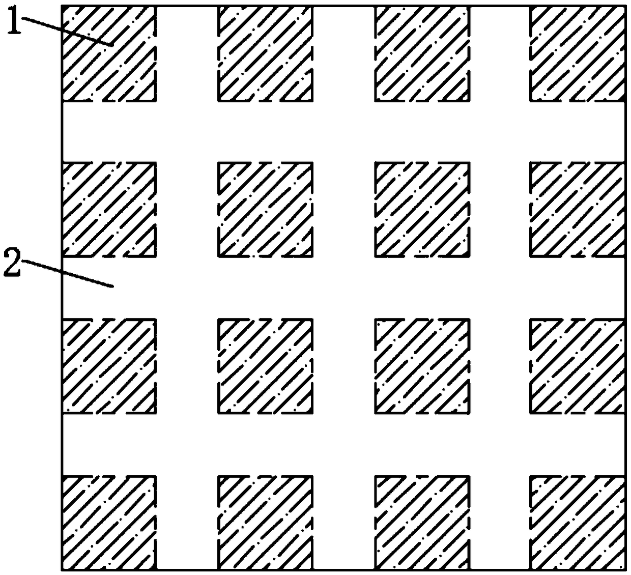
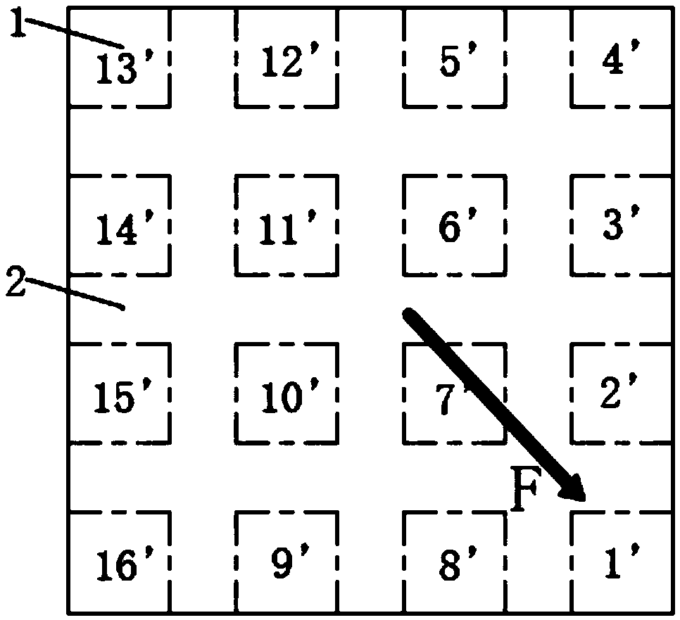
[0036] In this embodiment, the number of piezoelectric polymers 1 is 16, arranged uniformly in 4×4, numbered 1', 2', 3', 4', 5', 6', 7', 8', 9', 10', 11', 12', 13', 14', 15' and 16';

[0037] The method of detecting the magnitude of the shear force: image 3 When there is a shear force F at the position in , the piezoelectric polymers numbered 1'-16' all have charge output. When the magnitude of the shear force changes, the output charge of each numbered piezoelectric polymer also changes. When the shear force increases, the output charge also increases, and vice versa. The magnitude of the shearing force is detected by calibrating the electric charge output by the piezoelectric polymer and the shearing force.

[0038] To detect the direction of shear force: image 3 When there is a shear force F at the position in , all piezoelectric polymers 1 have charge output, and the algebraic difference is made for the charge values ​​output by all piezoelectric polymers 1, and the t...

Embodiment 2

[0041] In this embodiment, the number of piezoelectric polymers 1 is 4, which are evenly arranged in 2×2, numbered 1", 2", 3" and 4" respectively; the piezoelectric polymer 1 is coated with electrodes on the upper and lower surfaces PVDF piezoelectric film;

[0042] The charge of the piezoelectric polymer number 1" corresponds to Figure 5 In charge 1, number 2" corresponds to the amount of charge in the piezoelectric polymer Figure 5 The charge in the charge 2, number 3" corresponds to the charge amount of the piezoelectric polymer Figure 5 The charge in the charge 3, number 4" corresponds to the charge amount of the piezoelectric polymer Figure 5 The charge in 4. Figure 5 The examples shown show that the output charge of each piezoelectric polymer 1 increases with the increase of the shear force. The charge value output by the piezoelectric polymer No. 2" is the largest, that is, the location where the shear force acts is close to it.

[0043] Charge 13 means the al...


PUM

PropertyMeasurementUnit
Thicknessaaaaaaaaaa
Thicknessaaaaaaaaaa

Abstract

The invention discloses a planar array type shear force touch sensor and a shear force parameter detection method. The sensor comprises piezoelectric polymers, an upper-layer substrate and a lower-layer substrate, wherein the piezoelectric polymer are identical and are arranged in an array manner, and a distance between every two adjacent piezoelectric polymers in all directions is the same; all the piezoelectric polymers are uniformly fixed between the upper-layer substrate and the lower-layer substrate; and a conductive material is coated on positions, which are in contact with the piezoelectric polymers, of the lower surface of the upper-layer substrate and the upper surface of the lower-layer substrate, and the piezoelectric polymers are connected to an external charge amplifier through the conductive material. According to the method, the size, direction and action position of the shearing force can be detected at the same time based on the planar array type shear force touch sensor. The whole sensor adopts a planar structure, and is simple in structure, high in sensitivity, short in manufacturing period, stable in performance, long in service life and easy to popularize.

Description

technical field [0001] The invention relates to the field of tactile sensors, in particular to a planar array shear force tactile sensor and a shear force parameter detection method. Background technique [0002] The tactile sensor is an effective way for humans and intelligent robots to feel the external environment. Tactile perception is essential for three behaviors of operation, detection, and response. The importance of tactile sense for the operation of intelligent robots is most obvious in fine movements. Tactile perception allows the robot to continuously receive tactile information about materials and surface features, such as hardness, thermal conductivity, friction, roughness, etc., to help it better recognize objects. With the progress of the times, tactile sensors are increasingly widely used in fields such as health care, sports, and robotics. [0003] When the robot completes actions such as grasping and clamping, it needs to detect the three-dimensional forc...

Claims


Application Information

Patent Timeline
IPC IPC(8): G01L1/16
CPCG01L1/16
Inventor 刘吉晓杨宏伟郭士杰王曼菲刘娜
Owner HEBEI UNIV OF TECH
Why Eureka
Try Eureka