Built-in piano key motion detection device

A motion detection, built-in technology, applied to instruments, electro-acoustic musical instruments, etc., can solve the problems of complex circuits, high cost, poor stability, etc., and achieve the effect of simple circuits and systems, low structural cost, and high stability

Pending Publication Date: 2018-12-21
飞来教育科技(深圳)有限公司
View PDF4 Cites 0 Cited by
  • Summary
  • Abstract
  • Description
  • Claims
  • Application Information

AI Technical Summary

Problems solved by technology

The main disadvantages are: it takes up the space of the keys, especially the black keys (which are relatively short), which affects normal playing; the structure is fixed and unstable, which is easy to generate noise and interfere with the sound of the piano; the device is external, which affects the appearance; the white keys use reflective photoelectric sensors , the black key adopts a through-beam photoelectric sensor, which has a complex structure, and can only detect the key switch action, but cannot detect more information such as playing strength; the multi-channel single-chip microcomputer system has complex circuits and high cost;
The main disadvantage is: poor compatibility
The height, position, arrangement, and angle of different piano actions are different. Although the position of the light sensor can be adjusted, the overall compatibility is poor; the structure is expensive but the stability is poor, and it is easy to deform and damage due to gravity; it is difficult to accurately Detect more information such as playing strength; multi-channel single-chip microcomputer system, complex circuit and high cost

Method used


Image

  • Built-in piano key motion detection device
  • Built-in piano key motion detection device
  • Built-in piano key motion detection device

Examples


Embodiment Construction

[0032] The present invention will be described in further detail below in conjunction with the accompanying drawings.

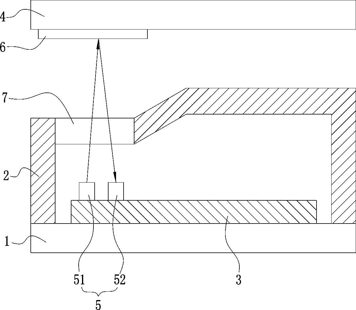
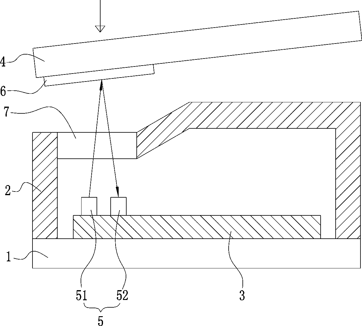
[0033] like Figure 1-2 As shown, a built-in piano key action detection device, which is installed under the keyboard of the piano key 4; includes a housing, in which a PCB board 3 is provided, and a plurality of photoelectric sensors 5, a plurality of groups of switch modules, A single-chip microcomputer, a detection circuit and a bluetooth module, each group of switch modules is correspondingly connected to a plurality of photoelectric sensors 5, and a photoelectric sensor 5 corresponds to a piano key 4; a window is provided on the housing, and a lens 7 is arranged on the window, and the photoelectric sensor 5 includes a photoelectric transmitter 51 and photoelectric receiver 52. The housing includes a bottom plate 1 and a casing 2 , the PCB board 3 is fixed on the bottom plate 1 , and the casing 2 covers the PCB board 3 . The bottom plate 1 is a metal pl...


PUM


Abstract

The invention discloses a built-in piano key motion detection device arranged below a keyboard and comprising a housing; a PCB plate is arranged in the housing, and provided with a plurality of photoelectric sensors, a plurality of switch modules, a single chip, a detection circuit, and a Bluetooth module; each switch module is correspondingly connected with a plurality of photoelectric sensors; each photoelectric sensor is matched with a key; the housing is provided with a window that has a lens; the photoelectric sensor comprises a photoelectric emitter and a photoelectric receiver; the photoelectric emitter emits a light that penetrates the lens, the light is reflected by the key bottom and penetrates the lens, and is received by the photoelectric receiver; the photoelectric receiver converts the received optical signal into an electric signal, the electric signal is amplified and detected by the detection circuit, and transmitted to the single chip; the single chip forms a MIDI signal that is uploaded by the Bluetooth module to a terminal. The detection device fully employs the reflective photoelectric sensor, and uses the single channel single chip solution; only one single chip program is compiled and burned, thus controlling 11 sets of reuse switches to move for detection. The circuit is simple and efficiency, and the element cost and the production cost are rather low.

Description

technical field [0001] The invention relates to the technical field of piano accessories, in particular to a built-in piano key movement detection device. Background technique [0002] According to the difference in internal structure and sound production principle, pianos on the market can be divided into two categories: one is traditional piano (also known as mechanical piano or acoustic piano), and the other is electronic piano (also known as electric piano or digital piano). [0003] In a traditional piano, the fingers strike the keys, which are transmitted through a lever, and the action is driven to strike the strings to produce sound. Traditional pianos have complex structures, high purchase and maintenance costs, and poor function expansion, but they have good timbre and feel, and are suitable for professional performances. [0004] The electronic piano is a finger hitting the keys, and the internal circuit detects and simulates the sound. The structure of the elec...

Claims


Application Information

Patent Timeline
Patent Type & Authority Applications(China)
IPC IPC(8): G10H1/34G10H1/00
CPCG10H1/0066G10H1/34
Inventor 曾延寿
Owner 飞来教育科技(深圳)有限公司
Why Eureka
Try Eureka