
Composite grounding cable

A composite grounding and cable technology, applied in the direction of cables, insulated cables, connecting contact materials, etc., can solve the problem that the grounding cable is not easy to be corroded, and achieve the effect of good grounding effect, good corrosion resistance and simple structure

Pending Publication Date: 2018-12-21
武汉中洋博宇科技发展有限公司
View PDF0 Cites 0 Cited by
  • Summary
  • Abstract
  • Description
  • Claims
  • Application Information

AI Technical Summary

Problems solved by technology

[0004] The purpose of the present invention is to provide a composite grounding cable to solve the problem that the existing grounding cables are not easy to be corroded

Method used


Image

  • Composite grounding cable
  • Composite grounding cable
  • Composite grounding cable

Examples


Embodiment 1

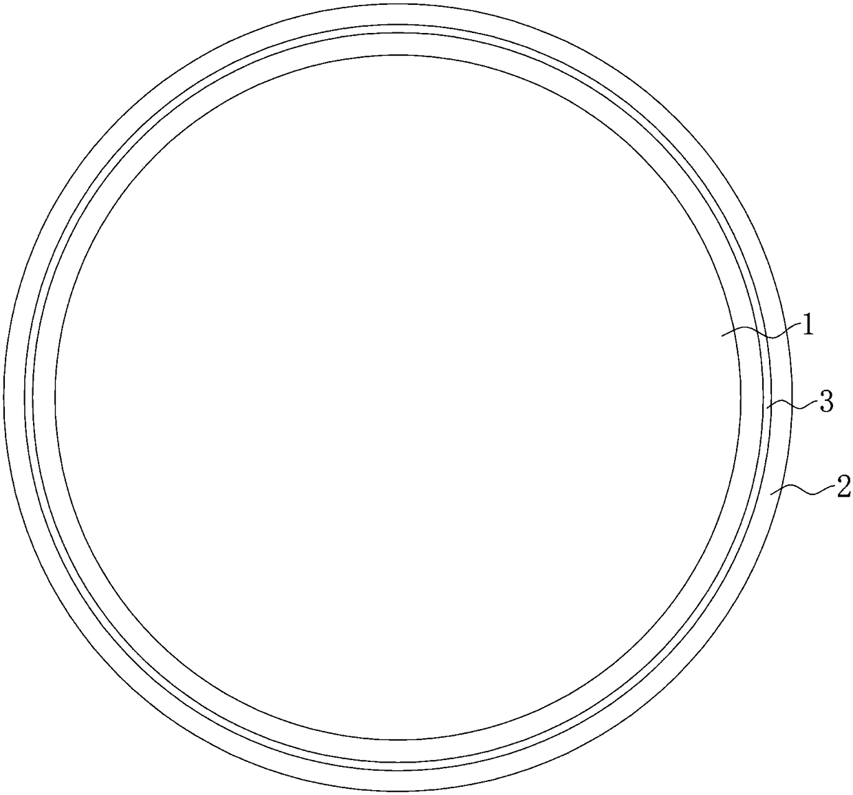
[0027] Such as figure 1 As shown, the present invention provides a composite grounding cable, which includes a grounding cable 1 and a first anti-corrosion layer 2 coated on the outside of the grounding cable 1 . The grounding cable 1 is made of simple metal or alloy metal. In order to improve the corrosion resistance of the conductor, many existing grounding bodies usually use graphite and other non-metallic materials with good corrosion resistance to weave the grounding body. The ability to withstand high-current short-circuit is poorer than that of metal conductors, so the grounding cable 1 of this scheme is selected as a metal body with a diameter ranging from 5-10mm, and the first anti-corrosion layer 2 is extruded on the outer wall of the grounding cable 1 The conductive layer on the top makes the inside of the first anti-corrosion layer 2 form a seal without leakage, so that the grounding cable 1 is completely isolated from the outside world, preventing it from being ox...

Embodiment 2

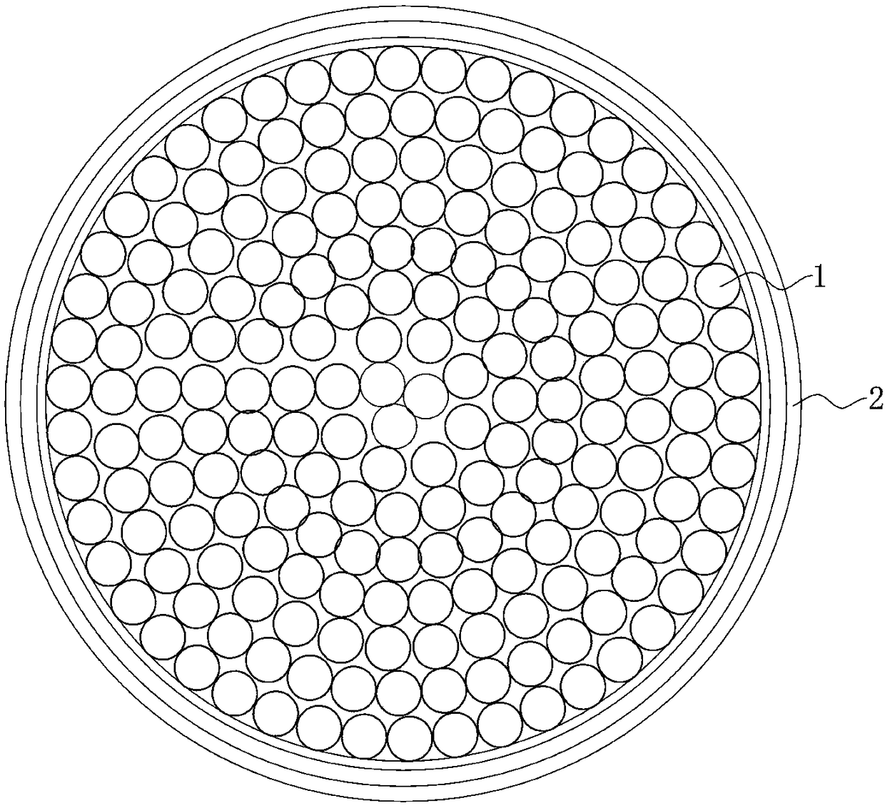
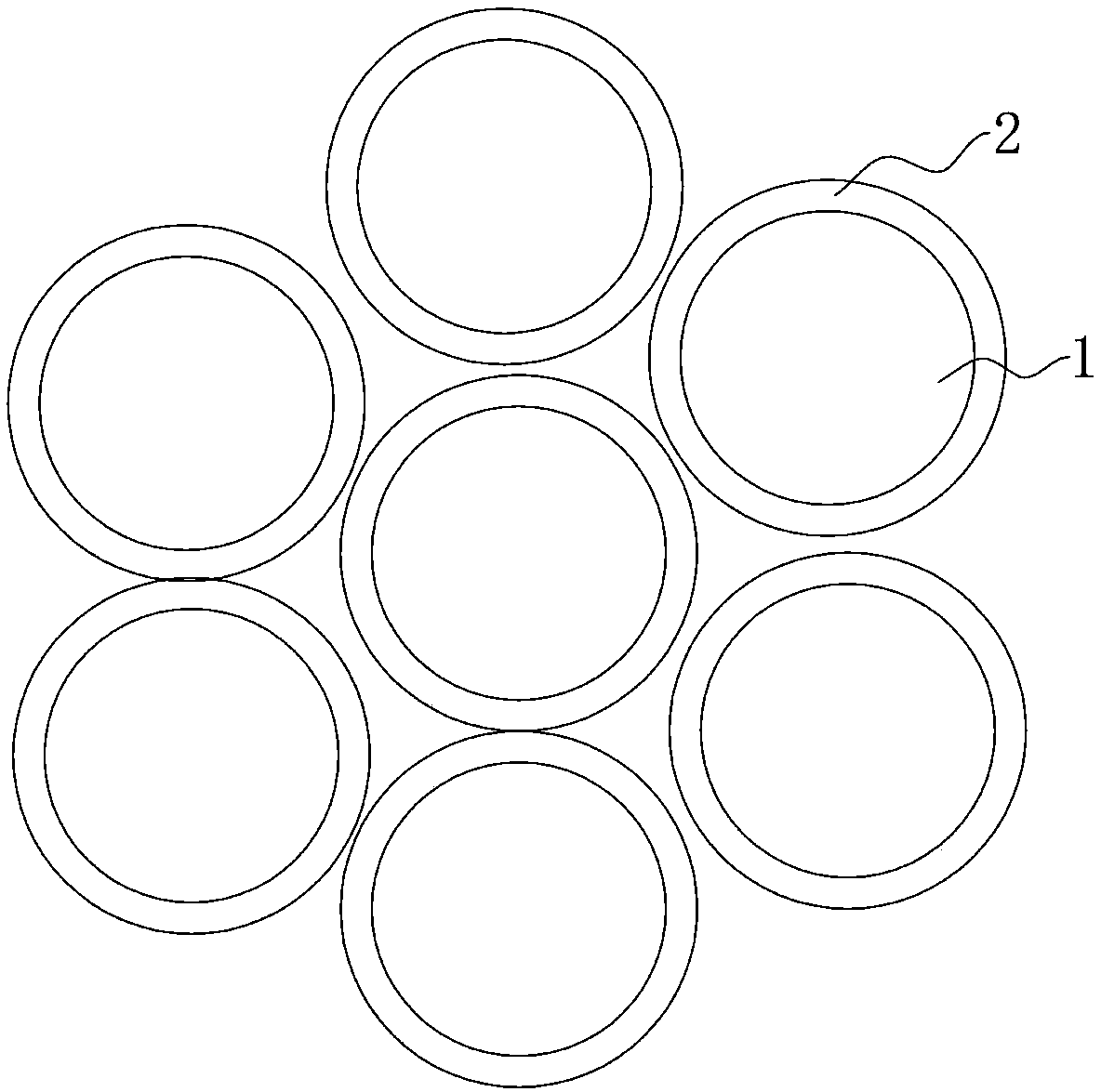
[0029] The difference from Embodiment 1 is that the grounding cable 1 is formed by a tight bundle of multiple metal wires, wherein the multiple metal wires are distributed in a linear array or a circular array, and the twisted structure of multiple metal wires makes each The copper core wires are tightly wound and arranged stably to obtain a relatively ideal overall mechanical strength and stable electrical properties of the cable; and to maintain a certain flexibility of the cable to meet the actual needs of various laying constructions and meet the needs of multiple electrical equipment. For equipotential connection, the number and diameter of metal wires can be designed and adjusted according to specific usage conditions. Similarly, the material of metal wires can also be designed as aluminum core wire, steel core wire, etc. according to the electrical performance index of grounding. Metal core wire. A second anti-corrosion layer 4 is also plated on the outer wall of each w...


PUM

PropertyMeasurementUnit
diameteraaaaaaaaaa

Abstract

The invention discloses a composite grounding cable which comprises a grounding cable and a first anticorrosion layer wrapped on the outside of the grounding cable, The first anticorrosion layer is anelectrically conductive layer extruded on the outer wall of the grounding cable to form a seal inside the first anticorrosion layer, and at least one first anticorrosion layer is arranged, the grounding cable is made of metal simple substance or alloy metal, and the first anticorrosion layer is an electrically conductive rubber layer or an electrically conductive plastic layer. The composite ground cable of the invention is coated with one or more conductive anticorrosive layers on the surface of the ground cable, The conductive rub or the conductive plastic has good corrosion resistance, thereby ensuring that the electrical conductivity of the grounding cable covered by the anticorrosion layer is not easy to reduce conductivity due to external environmental corrosion. At the same time, the grounding cable adopts metal conductor, which has strong ability of resisting short circuit of large current. Even in the soil with high grounding resistance, the grounding cable can disperse lightning energy effectively. The structure is simple, the grounding effect is good, and the use is convenient.

Description

technical field [0001] The invention relates to the technical field of lightning protection and grounding of power systems, in particular to a composite grounding cable. Background technique [0002] In the electrified railway system, the grounding performance and reliability of the grounding device not only affect the normal and effective operation of electrical equipment, communication equipment and other electrical facilities and personal safety, but also directly affect the timeliness and accuracy of railway control signals and communication signals. , Reliable delivery. Therefore, the railway grounding device is also very important to the safe, high-speed and planned operation of the railway locomotive. [0003] At present, the grounding cables of railway grounding devices are all bare cables made of a single metal material such as copper or steel, and these metal grounding cables are buried underground or connected between electrical facilities during use. The ground...

Claims


Application Information

Patent Timeline
Patent Type & Authority Applications(China)
IPC IPC(8): H01B7/00H01B7/28H01R4/66
CPCH01R4/66H01B7/0009H01B7/0045H01B7/2806
Inventor 侯波史向平房灵光汪绍华
Owner 武汉中洋博宇科技发展有限公司
Learn More