A magnetic tunnel junction
A magnetic tunnel junction, non-magnetic technology, applied in the field of non-volatile storage and logic, can solve the problems of low tunneling magnetoresistance and can not meet the requirements of industrialization
- Summary
- Abstract
- Description
- Claims
- Application Information
AI Technical Summary
Problems solved by technology
Method used
Image
Examples
Embodiment 1
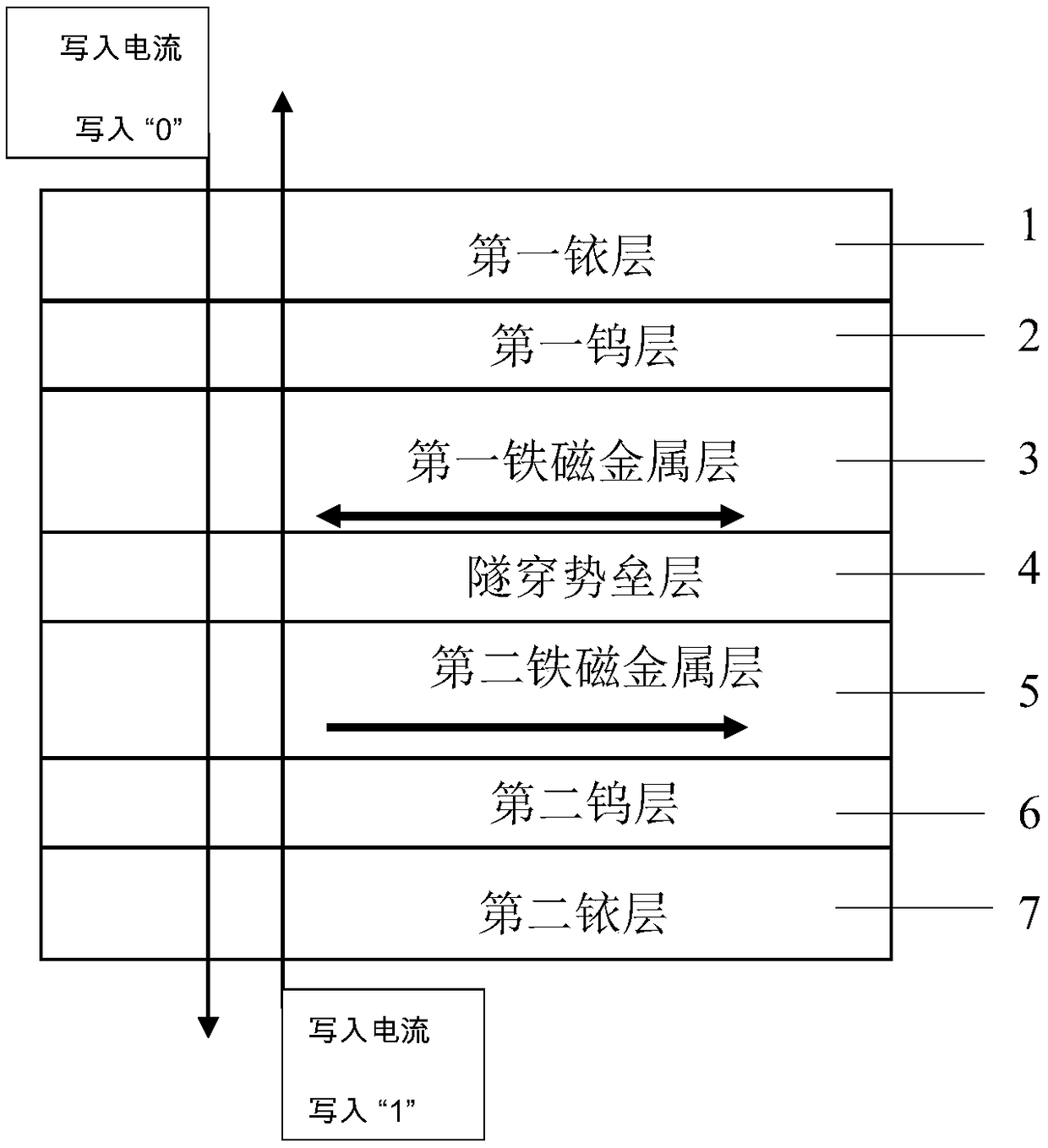
[0026] figure 1 It is a schematic diagram of the core structure of a magnetic tunnel junction. The core structure of the present invention from top to bottom is "first iridium layer / first tungsten layer / first ferromagnetic metal layer / tunneling barrier layer / second ferromagnetic metal layer / second tungsten layer / second iridium layer ". The first iridium layer 1 is the top electrode. The first tungsten layer 2 is a covering layer, which protects the first ferromagnetic metal layer 3 from being oxidized. The first ferromagnetic metal layer 3 is a free layer, and the magnetization direction of the first ferromagnetic metal layer 3 is reversed by using spin transfer torque by passing a write current in the vertical direction of the magnetic tunnel junction. When a top-down write current is applied, the magnetic tunnel junction changes from an antiparallel state to a parallel state, becoming a low-resistance state, and "0" is written; when a bottom-up write current is applied, t...
Embodiment 2
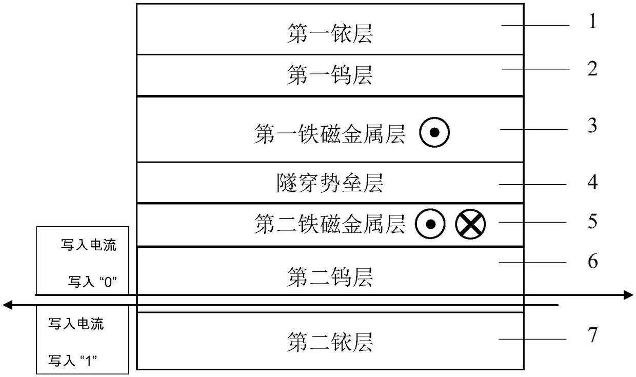
[0030] figure 2It is a schematic diagram of the core structure of a magnetic tunnel junction. The core structure of the present invention from top to bottom is "first iridium layer / first tungsten layer / first ferromagnetic metal layer / tunneling barrier layer / second ferromagnetic metal layer / second tungsten layer / second iridium layer ". The first iridium layer 1 is the top electrode. The first tungsten layer 2 is a covering layer, which protects the first ferromagnetic metal layer 3 from being oxidized. The first ferromagnetic metal layer 3 is a reference layer, and its magnetization direction is fixed. The tunneling barrier layer 4 is used to generate tunneling current. The second ferromagnetic metal layer 5 is a free layer whose magnetization direction can be changed. The second tungsten layer 6 is a seed layer for optimizing the growth process of the second ferromagnetic metal layer 5 . The second iridium layer 7 is the bottom electrode. The electrodes are drawn out o...
Embodiment 3
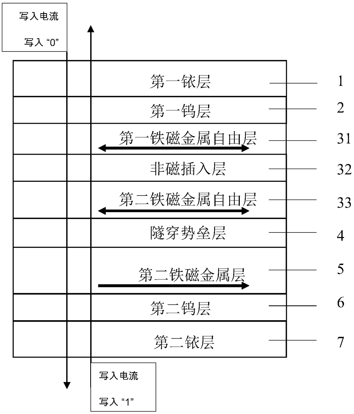
[0034] image 3 It is a schematic diagram of the core structure of a magnetic tunnel junction. The core structure of the present invention from top to bottom is "first iridium layer / first tungsten layer / first ferromagnetic metal free layer / non-magnetic insertion layer / second ferromagnetic metal free layer / tunneling barrier layer / second Ferromagnetic metal layer / second tungsten layer / second iridium layer" structure. Wherein, the overall structure of "first ferromagnetic metal free layer / nonmagnetic insertion layer / second ferromagnetic metal free layer" is a free layer, and the second ferromagnetic metal layer is used as a reference layer. The first iridium layer 1 is the top electrode. The first tungsten layer is the covering layer 2, which protects the first ferromagnetic metal free layer 31 from being oxidized. The non-magnetic insertion layer 32 is used for ferromagnetic coupling between the first ferromagnetic metal free layer 31 and the second ferromagnetic metal free l...
PUM
| Property | Measurement | Unit |
|---|---|---|
| thickness | aaaaa | aaaaa |
| thickness | aaaaa | aaaaa |
| thickness | aaaaa | aaaaa |
Abstract
Description
Claims
Application Information
 - R&D
- Intellectual Property
- Life Sciences
- Materials
- Tech Scout
- Unparalleled Data Quality
- Higher Quality Content
- 60% Fewer Hallucinations
Browse by: Latest US Patents, China's latest patents, Technical Efficacy Thesaurus, Application Domain, Technology Topic, Popular Technical Reports.
© 2025 PatSnap. All rights reserved.Legal|Privacy policy|Modern Slavery Act Transparency Statement|Sitemap|About US| Contact US: help@patsnap.com


