Motor rotor cool structure

A technology for motor rotors and cooling structures, applied in cooling/ventilation devices, electromechanical devices, electrical components, etc., can solve problems such as limiting cooling capacity, damage, and friction on the inner wall of semi-hollow shafts, preventing friction and damage, and increasing contact. area, the effect of enhancing the heat dissipation effect

Active Publication Date: 2018-12-21
HUAZHONG UNIV OF SCI & TECH
View PDF5 Cites 10 Cited by
  • Summary
  • Abstract
  • Description
  • Claims
  • Application Information

AI Technical Summary

Problems solved by technology

However, in this way, the contact area between the cooling medium and the inner wall of the semi-hollow shaft is small, which greatly limits its cooling capacity
In addition, due to the axial insertion of the cooling pipe into the semi-hollow shaft, the formed cantilever structure may cause the cooling pipe to protrude into the semi-hollow shaft side to have a large deformation, thereby contacting the inner wall of the semi-hollow shaft to cause friction and damage

Method used


Image

  • Motor rotor cool structure
  • Motor rotor cool structure

Examples


Embodiment Construction

[0025] In order to make the object, technical solution and advantages of the present invention clearer, the present invention will be further described in detail below in conjunction with the accompanying drawings and embodiments. It should be understood that the specific embodiments described here are only used to explain the present invention, not to limit the present invention. In addition, the technical features involved in the various embodiments of the present invention described below can be combined with each other as long as they do not constitute a conflict with each other.

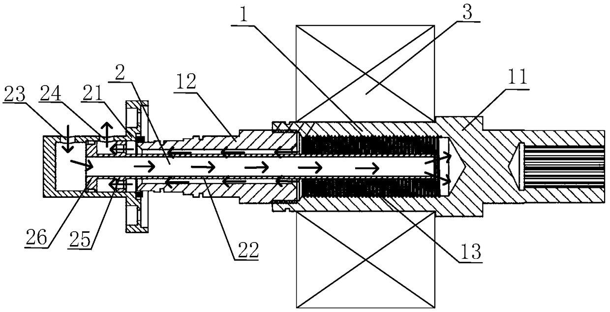
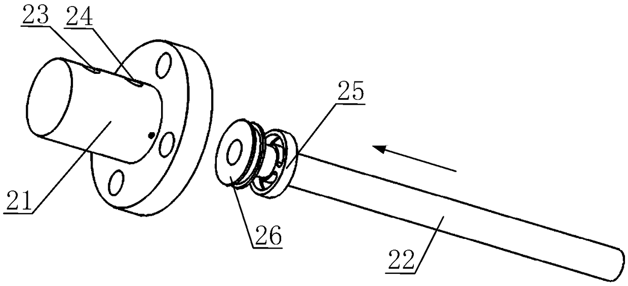
[0026] The invention provides a motor rotor cooling structure. The overall idea is to make the semi-hollow shaft have an internal cavity with an enlarged closed end, thereby increasing the heat dissipation area and effectively preventing the contact and friction between the end of the cooling pipe and the inner wall of the semi-hollow shaft. Structural damage.

[0027] Such as figure 1 As show...


PUM


Abstract

The invention discloses a motor rotor cooling structure, comprising: a half hollow shaft, a cooling pipe assembly and a motor rotor; The half hollow shaft has a half hollow structure and an internal cavity with a closed end enlarged; The motor rotor is sleeved on the half hollow shaft and close to the closed end of the half hollow shaft; The cooling tube assembly includes an interconnected coolingtube head and a cooling pipe; The opening end of the cooling tube head and the half hollow shaft is connected by a dynamic seal and fixed on the motor end cover, and an inlet and an outlet are also arranged on the cooling tube head and the half hollow shaft. An outer diameter of the cooling pipe is smaller than an inner diameter of an open end of the half hollow shaft and is axially inserted intoa cavity of the half hollow shaft, thereby forming a cooling passage between an outer wall of the cooling pipe and an inner wall of the semi-hollow shaft. The invention can effectively increase the heat dissipation area and effectively prevent the end of the cooling pipe from contacting the inner wall of the half hollow shaft due to the deformation of the cantilever structure.

Description

technical field [0001] The invention belongs to the technical field of motor cooling, and more specifically relates to a motor rotor cooling structure. Background technique [0002] High-speed motors have the advantages of high power density, high efficiency, and compact size, so they are widely used in industrial fields such as aircraft starters / generators, flywheel energy storage, high-speed electric spindles, superchargers in the petrochemical field, and industrial air compressors / blowers. . However, due to the high-speed operation of the motor, the rotor loss (including electromagnetic loss and mechanical loss) of the motor is usually very large. Larger rotor losses will cause the motor rotor and bearings to heat up, reduce the life of the bearings, and affect the safe and stable operation of the motor. [0003] In order to reduce the rotor temperature, the rotor needs to be cooled. The rotor is usually cooled by air cooling, but the cooling capacity of air cooling is...

Claims


Application Information

Patent Timeline
Patent Type & Authority Applications(China)
IPC IPC(8): H02K9/19H02K7/00
CPCH02K7/003H02K9/19H02K9/197
Inventor 李大伟范兴纲曲荣海王聪房莉
Owner HUAZHONG UNIV OF SCI & TECH
Why Eureka
Try Eureka