Novel road crash barrier

An anti-collision guardrail and guardrail technology, which is applied to roads, roads, road safety devices, etc., can solve the problems of buffer effect and protection degree limitation, vehicle paint surface wear, etc., to improve service life, improve strength, and reduce interface holes. and defect effects

Inactive Publication Date: 2018-12-25
崔文琦
View PDF0 Cites 0 Cited by
  • Summary
  • Abstract
  • Description
  • Claims
  • Application Information

AI Technical Summary

Problems solved by technology

[0003] Most of the current buffer guardrails are composed of wavy metal protective belts and support rods. The top of the support rods is tightly connected with the wavy metal protective belts by fastening bolts, and the bottom of the support rods is fixedly connected with the ground; , the vehicle acts as a buffer under the action of the protective belt to reduce the damage caused by the impact force; since the protective belt is made of metal and there is no other structure on the surface, the cushioning effect can only be limited by its own material and shape structure in the event of an impact ; Moreover, in the event of a slight collision, it is easy to cause abrasion to the paint surface of the vehicle, and the cushioning effect and protection degree are limited to a certain extent.

Method used


Image

  • Novel road crash barrier
  • Novel road crash barrier

Examples


Embodiment 1

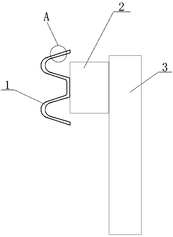
[0029] refer to Figure 1 to Figure 2 , the present invention includes a wavy guardrail 1;

[0030] The guardrails 1 are connected horizontally head-to-tail, and the head-to-tail connections are fastened to one side of the buffer ring 2 through fastening bolts; the other side of the buffer ring 2 is fastened to the support column 3;

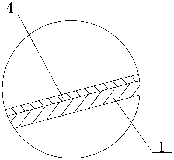
[0031] A buffer layer 4 is provided on the outside of the guardrail.

Embodiment 2

[0033] In order to improve the elasticity, strength and aging resistance of the buffer layer, the present invention improves the material of the buffer layer. Specifically, the buffer layer is prepared according to the following steps:

[0034] Step 1) Weigh raw materials: 100 parts of butadiene rubber, 30 parts of polypropylene resin, 10 parts of phenolic resin, 8 parts of urea-formaldehyde resin, 5 parts of vulcanizing agent sulfur, 3 parts of dioctyl phthalate, 3 parts of diatomaceous earth , 2 parts of hexamethylcyclotrisiloxane, 2 parts of glass fiber, 1 part of stearic acid, 1 part of talcum powder;

[0035] Step 2) Diatomite modification: Put the diatomite into a heating furnace for high-temperature calcination. The temperature in the heating furnace is 750°C, and the calcination time is 30 minutes. Take it out, cool it to room temperature, and then add hexamethylcyclotrisil Oxygen, heated to 80°C, ultrasonic dispersion treatment for 5 minutes under heat preservation co...

Embodiment 3

[0040] In order to improve the elasticity, strength and aging resistance of the buffer layer, the present invention improves the material of the buffer layer. Specifically, the buffer layer is prepared according to the following steps:

[0041] Step 1) Weigh raw materials: 150 parts of butadiene rubber, 50 parts of polypropylene resin, 15 parts of phenolic resin, 12 parts of urea-formaldehyde resin, 7 parts of vulcanizing agent sulfur, 5 parts of dioctyl phthalate, 5 parts of diatomaceous earth , 3 parts of hexamethylcyclotrisiloxane, 3 parts of glass fiber, 2 parts of stearic acid, 1 part of talcum powder;

[0042] Step 2) Diatomite modification: Put the diatomite into a heating furnace for high-temperature calcination. The temperature in the heating furnace is 750°C, and the calcination time is 30 minutes. Take it out, cool it to room temperature, and then add hexamethylcyclotrisiloxane Alkanes, heated to 80 ° C, under the condition of heat preservation, ultrasonic dispersio...


PUM


Abstract

The invention discloses a novel road anti-collision guardrail, which comprises wave-shaped guardrails, wherein, the guardrails are connected with each other transversely, end to end correspondingly, and with the corresponding connection positions end to end are connected with one side of a buffer ring through fastening bolts. The other side of the buffer ring is mutually tightly connected with thesupport column; The outer side of the guard rail is provided with a buffer layer. The buffer layer can improve the strength of the protective fence, effectively absorb the impact force, and reduce the scratch on the paint surface of the vehicle.

Description

technical field [0001] The invention belongs to the technical field of road traffic facilities, and in particular relates to a novel road anti-collision barrier. Background technique [0002] In the prior art, guardrails are often arranged on both sides of the road to prevent the vehicle from colliding and reduce the impact force, especially buffer guardrails are set on both sides of the expressway. [0003] Most of the current buffer guardrails are composed of wavy metal protective belts and support rods. The top of the support rods is tightly connected with the wavy metal protective belts by fastening bolts, and the bottom of the support rods is fixedly connected with the ground; , the vehicle acts as a buffer under the action of the protective belt to reduce the damage caused by the impact force; since the protective belt is made of metal and there is no other structure on the surface, the cushioning effect can only be limited by its own material and shape structure in th...

Claims


Application Information

Patent Timeline
Patent Type & Authority Applications(China)
IPC IPC(8): E01F15/02C08L9/00C08L23/12C08L61/06C08L61/24C08K13/04C08K7/26C08K7/14C08K5/12C08K3/06
CPCE01F15/02C08L9/00C08L2205/02C08L2205/035C08L23/12C08L61/06C08L61/24C08K13/04C08K7/26C08K7/14C08K5/12C08K3/06
Inventor 崔文琦
Owner 崔文琦
Why Eureka
Try Eureka