Power tower pole base installation device
A technology for installing devices and foundations, applied in infrastructure engineering, excavation, construction, etc., can solve undisclosed problems and achieve the effect of ensuring stability and ensuring stability
- Summary
- Abstract
- Description
- Claims
- Application Information
AI Technical Summary
Problems solved by technology
Method used
Image
Examples
Embodiment 1
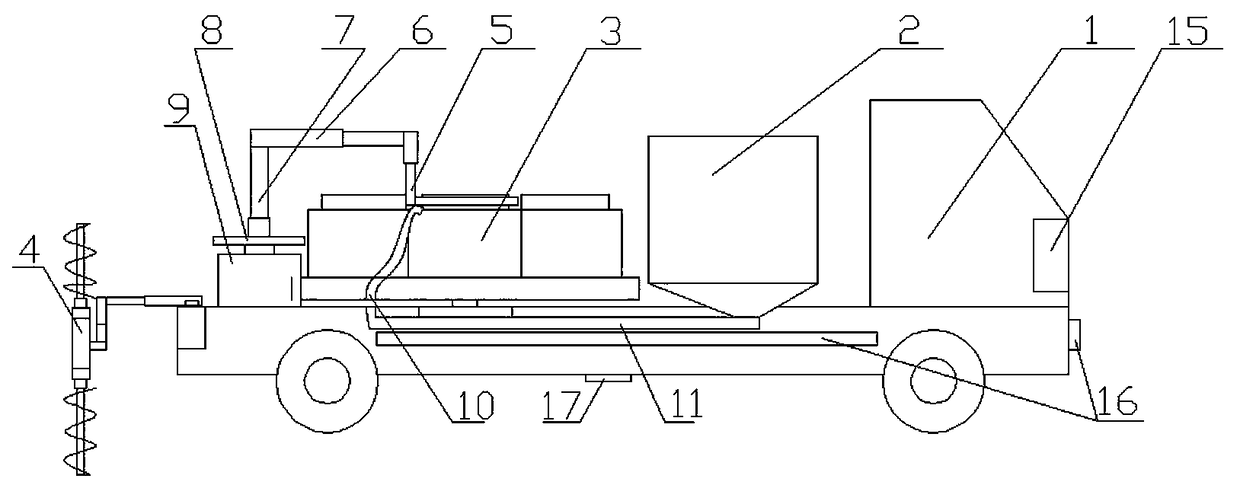
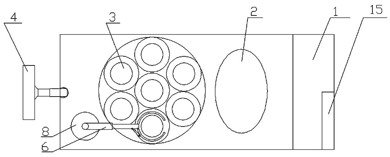
[0033] An installation device for the base of a power tower pole, comprising a mobile trolley 1, a foundation pit excavation mechanism 4 arranged on the mobile trolley 1, a bearing bin 3 arranged on the mobile trolley, arranged on the mobile trolley and connected with The installation mechanism matched with the bearing bin 3, the balance mechanism arranged on the mobile trolley 1 and matched with the foundation pit excavation mechanism 4, the pouring mechanism arranged on the mobile trolley 1 and matched with the installation mechanism , and a control mechanism 15 arranged on the mobile trolley for controlling the foundation pit excavation mechanism, the installation mechanism, the balance mechanism and the pouring mechanism;
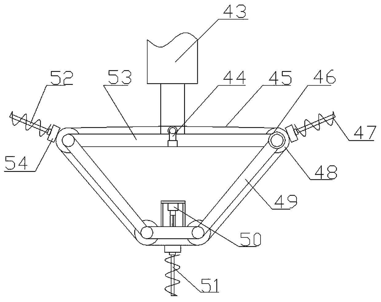
[0034] The foundation pit excavation mechanism 4 includes an excavation steering motor 41 arranged on the mobile trolley 1, a foundation pit telescopic arm 42 arranged on the output shaft of the excavation steering motor 41, and a telescopic arm 42 arran...
Embodiment 2
[0042] The difference from Embodiment 1 is that the balance mechanism includes a balance module arranged on each side of the mobile trolley 1 and a balance detection module 17 arranged in the middle of the mobile trolley 1;
[0043] The balance module includes a balance slide rail 18 arranged on the side of the mobile trolley, a balance screw 19 arranged on the side of the mobile trolley 1 and parallel to the balance slide rail 18, arranged on the balance wire The balance weight 20 on the bar 19 and matched with the balance slide rail 18, the balance bar 21 arranged on the balance weight 20, the counterweight bin 23 arranged at the end of the balance bar 21, and the balance bar 23 arranged on the balance bar 21. The water outlet pipe 35 at the lower end of the weight bin 23, the water inlet pipe 26 arranged on the top of the counterweight bin 23, the micro water pump 27 and the flow meter 28 arranged on the water outlet pipe 35 and the water inlet pipe 26 are arranged on the mo...
Embodiment 3
[0047] It differs from Embodiment 2 in that:
[0048] The auxiliary adjustment module 22 includes an inflatable chamber 221 arranged on the counterweight chamber 23, an inflatable bag 223 arranged on the inflatable chamber 221, arranged in the inflatable chamber 221 and matched with the inflatable bag 223 The pressure storage tank 224, the inflation solenoid valve 222 arranged on the pressure storage tank 224, the deflation solenoid valve 225 arranged on the side wall of the inflation chamber 221, and the cut-off electromagnetic valve arranged on the water outlet pipe 35 and the water inlet pipe 26 Valve 29.
[0049] The auxiliary adjustment module used in this embodiment is to ensure the stability of the structure, to avoid further adjustment when the counterweight bin cannot be adjusted during balance adjustment, and to reduce movement when passing through soft soil The pressure of the trolley on the ground makes it pass smoothly, avoiding the phenomenon that the vehicle ca...
PUM
 Abstract
Description
Claims
Application Information
 - R&D
- Intellectual Property
- Life Sciences
- Materials
- Tech Scout
- Unparalleled Data Quality
- Higher Quality Content
- 60% Fewer Hallucinations
Browse by: Latest US Patents, China's latest patents, Technical Efficacy Thesaurus, Application Domain, Technology Topic, Popular Technical Reports.
© 2025 PatSnap. All rights reserved.Legal|Privacy policy|Modern Slavery Act Transparency Statement|Sitemap|About US| Contact US: help@patsnap.com


