
Wastewater treatment device

A wastewater treatment, integrated technology, applied in multi-stage water treatment, water/sewage treatment, light water/sewage treatment, etc., can solve the problems of poor sewage treatment effect, affecting the service life of the device, difficult sewage purification treatment, etc.

Pending Publication Date: 2018-12-28
江苏瀚珹工程咨询有限公司
View PDF7 Cites 2 Cited by
  • Summary
  • Abstract
  • Description
  • Claims
  • Application Information

AI Technical Summary

Problems solved by technology

[0004] The object of the present invention is to provide a kind of waste water treatment device, in order to solve the problem that the sedimentation tank of the original sewage treatment equipment in the above-mentioned background technology adopts the mode of natural sedimentation, which causes the sludge that is easy to be taken away by the water flow to the filter screen The filter function of the filter is hindered, and it is not convenient to realize the filter function of the filter. During the electrolysis process, the impurity microorganisms in the sewage are easy to adhere to the surface of the electrode rod, which reduces the electrolysis effect of the electrode rod on the sewage, and it is difficult to purify the sewage. Disinfection box Disinfecting the purified water source by injecting drugs, it is difficult to control the dose of drugs, and it is easy to cause secondary pollution to the purified water source. There is no climbing device on the outside of the sewage treatment equipment, which makes it difficult for the maintenance personnel to realize the maintenance of the sewage treatment equipment. The problem is that the sewage is likely to contain corrosive substances. During the use of the device, it will inevitably cause corrosion to the device, which will eventually lead to poor sewage treatment effect and affect the service life of the device.

Method used


Image

  • Wastewater treatment device
  • Wastewater treatment device
  • Wastewater treatment device

Examples


Embodiment 1

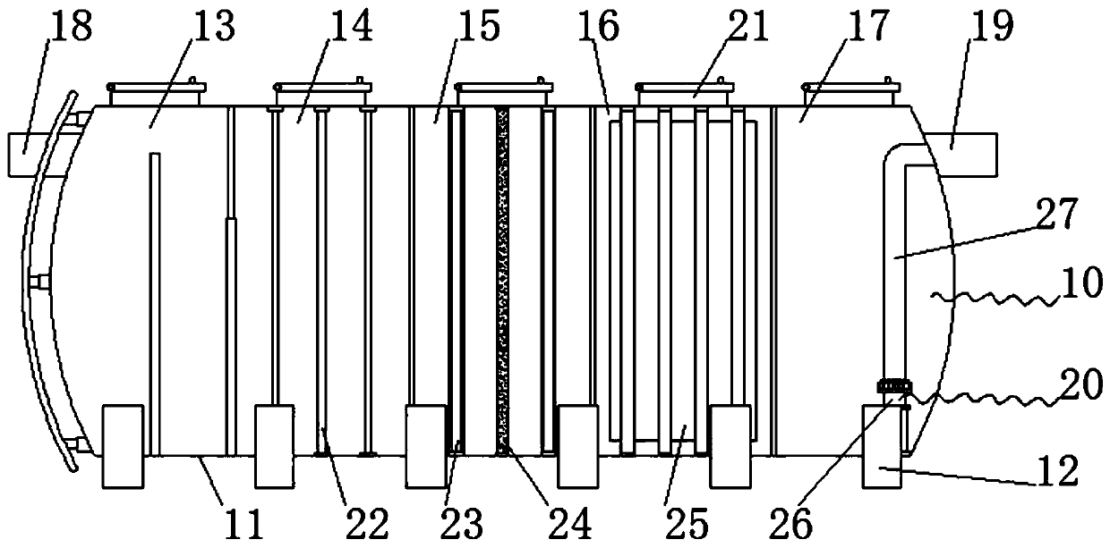
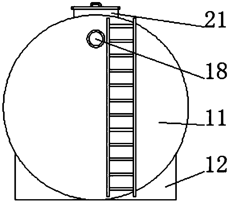
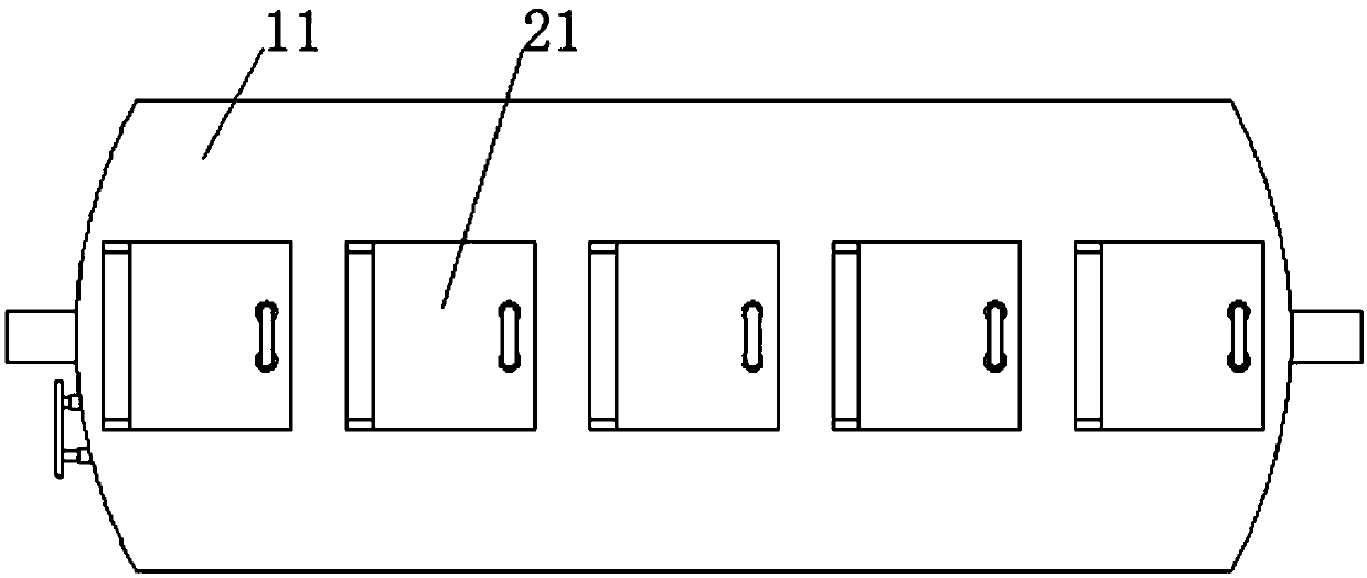
[0026] see Figure 1-3 , the present invention provides a technical solution: a wastewater treatment device, including a shell assembly 10, a functional assembly 20, the shell assembly 10 includes an integrated box 11, a base 12, a sedimentation box 13, a filter box 14, an electrolysis box 15, and a sterilization box 16 , clean water tank 17, water inlet pipe 18 and water outlet pipe 19, base 12 is provided below the outer side wall of the integrated case 11, the base 12 is fixedly connected with the integrated case 11, and the left side of the inner side wall of the integrated case 11 is provided with a sedimentation tank 13, and the sedimentation tank 13 is connected with the The integrated box 11 is fixedly connected, and the left side of the inner side wall of the integrated box 11 is close to the right side of the sedimentation box 13. There is a filter box 14, and the filter box 14 is fixedly connected with the integrated box 11. An electrolytic box 15 is arranged at the ...

Embodiment 2

[0041] The difference from Example 1 is that the surface of the shell assembly 10 is coated with a layer of anti-corrosion layer, and the preparation method of the anti-corrosion layer is:

[0042] Get the following components by weight for subsequent use: 20 parts of toluene cyclohexanone, 4 parts of talcum powder, 5 parts of heavy calcium carbonate, 12 parts of epoxy resin, 10 parts of tri-o-cresol phosphate, 3 parts of dammar resin, 7 parts of iron powder, 10 parts of pottery clay, 20 parts of deionized water.

[0043] S1. Prefabricated organic solvent: mix toluene cyclohexanone, epoxy resin, tri-o-cresol phosphate, and dammar resin, heat to 60°C, stir evenly, and keep warm for 4 hours;

[0044] S2. Preparation of anti-corrosion coating: add clay, iron powder, heavy calcium carbonate, talcum powder, and deionized water to the organic solvent in S1 in sequence, stir evenly, heat the temperature to 70° C., and keep it warm for 2 hours;

[0045] S3, processing: the anticorros...

Embodiment 3

[0050] The difference from Example 2 is that the formula of the anti-corrosion layer is modified and recoated on the shell assembly 10:

[0051] Get the following raw materials of each component by weight for subsequent use: 30 parts of toluene cyclohexanone, 6 parts of talcum powder, 8 parts of heavy calcium carbonate, 16 parts of epoxy resin, 12 parts of tri-o-cresol phosphate, 4 parts of dammar resin, 8 parts of iron powder, 15 parts of pottery clay, 24 parts of deionized water.

[0052] S1. Prefabricated organic solvent: mix toluene cyclohexanone, epoxy resin, tri-o-cresol phosphate, and dammar resin, heat to 60°C, stir evenly, and keep warm for 4 hours;

[0053] S2. Preparation of anti-corrosion coating: add clay, iron powder, heavy calcium carbonate, talcum powder, and deionized water to the organic solvent in S1 in sequence, stir evenly, heat the temperature to 70° C., and keep it warm for 2 hours;

[0054] S3, processing: the anticorrosion coating prepared in S2 is su...


PUM


Abstract

The invention discloses a wastewater treatment device. The wastewater treatment device comprises an outer shell component and a function component, the outer shell component comprises an integrated tank, a base, a precipitation tank, a filtering tank, an electrolysis tank, a sterilizing tank, a clear water tank, a water inlet pipe and a water outlet pipe, the base is arranged at the lower part ofthe outer side wall of the integrated tank and is fixedly connected with the integrated tank, a first baffle plate arranged on the inner side of the precipitation tank separates the precipitation tank, the sewage is precipitated and filtered twice in the precipitation tank, a second filter screen is arranged on the outer side of an electrode bar and prevents an impurity microorganism from adheringon the surface of the electrode bar and affecting the electrolysis and purification effects of the electrode bar on the sewage, sewage treatment equipment uses an ultraviolet lamp to emit ultravioletray to implement the sterilization operation, an escalator is arranged on the left side wall of the sewage treatment equipment, and an anticorrosive coating is coated on the outer shell component toprevent the outer shell component from being corroded by acid or alkaline sewage.

Description

technical field [0001] The invention belongs to the technical field of sewage treatment equipment, and in particular relates to a waste water treatment device. Background technique [0002] Sewage treatment equipment is a kind of industrial equipment that can prevent sewage and pollutants from flowing directly into waters, improve the ecological environment, enhance urban quality and promote economic development, and effectively treat urban domestic sewage and industrial wastewater. [0003] The sedimentation tank of the original sewage treatment equipment adopts the natural sedimentation method, which causes the sludge that is easily taken away by the water flow during the flow process to hinder the filtering function of the filter, which is not convenient for the realization of the filtering function of the filter. During the electrolysis process, the sewage The impurity microorganisms in the water are easy to adhere to the surface of the electrode rod, which reduces the e...

Claims


Application Information

Patent Timeline
Patent Type & Authority Applications(China)
IPC IPC(8): C02F9/06
CPCC02F9/00C02F1/001C02F1/32C02F1/46104C02F1/44C02F2001/007C02F2303/04C02F2303/14C02F2301/08
Inventor 樊璠
Owner 江苏瀚珹工程咨询有限公司
Learn More