Supercritical carbon dioxide based thermal stepped utilization method and system thereof

A carbon dioxide and supercritical technology, applied in steam applications, steam engine installations, machines/engines, etc., can solve the problems of increasing the complexity of the supercritical carbon dioxide cycle system, difficult to adapt to the load operating conditions, and increasing the difficulty of operation control, and achieve the The effect of shortening the running time under downtime conditions, improving economic competitiveness, and reducing the number of equipment

Inactive Publication Date: 2018-12-28
NUCLEAR POWER INSTITUTE OF CHINA
View PDF4 Cites 6 Cited by
  • Summary
  • Abstract
  • Description
  • Claims
  • Application Information

AI Technical Summary

Problems solved by technology

[0005] The technical problem to be solved by the present invention is: in the prior art, the method of adjusting the internal parameters of the cycle makes the system more complicated, more equipment, more difficult to adjust the operation, and it is also difficult to adapt to the problem of the rapid change of the load.
The object of the present invention is to provide a heat cascade utilization method and system based on supercritical carbon dioxide, which solves the system by introducing an external heat source without increasing the complexity of the supercritical carbon dioxide cycle system, without increasing the difficulty of operation control, and without increasing equipment. The problem of low heat recovery, improve efficiency

Method used


Image

  • Supercritical carbon dioxide based thermal stepped utilization method and system thereof

Examples


Embodiment 1

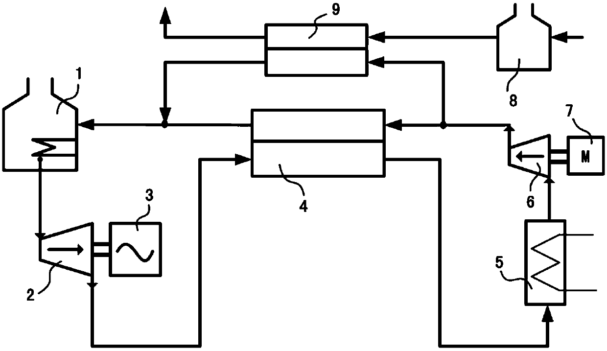
[0027] The cascade heat utilization method based on supercritical carbon dioxide includes passing the supercritical carbon dioxide through the high temperature heat source 1 turbine 2, the high temperature measurement of the main regenerator 4, the cooler 5, and the compressor 6, and then input to the main regenerator On the low temperature side of 4, the supercritical carbon dioxide in the low temperature side of the main regenerator 4 exchanges heat with the supercritical carbon dioxide in the high temperature measurement of the main regenerator 4 and then returns to the high temperature heat source 1 to form a cycle.

[0028] The circulation system contains two sets of independent heat sources: high temperature heat source 1 and medium and low temperature heat source 8. The supercritical carbon dioxide flowing through the compressor 6 is divided into two ways. One way supercritical carbon dioxide passes through the low temperature side of the main regenerator 4 for heat exchange...

Embodiment 2

[0030] A heat cascade utilization system based on supercritical carbon dioxide, including high temperature heat source 1, turbine 2, generator 3, main regenerator 4, cooler 5, compressor 6, electric motor 7, medium and low temperature heat source 8, branch regenerator 9 .

[0031] The high temperature heat source 1 is connected to the inlet of the turbine 2, the outlet of the turbine 2 is connected to the high temperature side inlet of the main regenerator 4, and the high temperature side outlet of the main regenerator 4 is connected to the inlet of the cooler 5. The cooler The outlet of 5 is connected to the inlet of compressor 6, and the outlet of compressor 6 is divided into two paths, one is connected to the low temperature side inlet of the main regenerator 4, and the other is connected to the low temperature side inlet of the branch regenerator 9 , The low-temperature side outlet of the main regenerator 4 merges with the low-temperature side outlet of the branch regenerator...


PUM


Abstract

The invention discloses Supercritical carbon dioxide based thermal stepped utilization method and system thereof which solves the problems featuring with various complicated cycles leading to more complicated system, more equipment and difficulties to operate to adapt to the operating conditions with rapidly changing loads due to the regulation mode of the internal parameters of cycles in the prior art. The invention comprises the step utilization method of heat based on supercritical carbon dioxide and also discloses its system. The system comprises high-temperature heat source 1, turbine 2,generator 3, main regenerator 4, cooler 5, compressor 6, electric motor 7, medium and low temperature heat source 8 and support regenerator 9. The invention solves the problem of low heat recovery ofthe prior system by introducing an external heat source without increasing the complexity of the supercritical carbon dioxide circulation system, thereby improving the efficiency by more than 10% andreducing the investment cost by more than 30%.

Description

Technical field [0001] The invention relates to the technical field of comprehensive utilization of heat, in particular to a method and system for cascade utilization of heat based on supercritical carbon dioxide. Background technique [0002] Supercritical carbon dioxide Brayton cycle power generation technology has received more and more attention in recent years. The basic equipment configuration of the supercritical carbon dioxide Brayton cycle system is heat source, compressor, turbine, cooler and regenerator. However, due to the different specific heats of the working fluid on both sides of the regenerator in this cycle, there is a theoretically large temperature difference between the two ends of the regenerator, and the increase in system entropy is relatively large, resulting in relatively low system efficiency. [0003] In order to solve the problem that the efficiency is difficult to improve due to the large temperature difference between the two ends of the regenerator...

Claims


Application Information

Patent Timeline
Patent Type & Authority Applications(China)
IPC IPC(8): F01K25/10F01K27/00F01K23/02F01K17/02
CPCF01K17/02F01K23/02F01K25/103F01K27/00
Inventor 王俊峰黄彦平
Owner NUCLEAR POWER INSTITUTE OF CHINA
Why Eureka
Try Eureka