Electric-driving transmission device for electric vehicle and control method

A technology of transmission and electric drive, applied in the direction of multi-ratio transmission, transmission, electric power device, etc., can solve the problem of not taking into account the power and economy of pure electric vehicles, affecting battery life and endurance, and reducing electric drive. Assembly system efficiency and other issues to achieve the effect of reducing axial size, reducing difficulty, and eliminating mechanical vibration

Inactive Publication Date: 2018-12-28
上海屹驱新能源科技有限责任公司
View PDF9 Cites 18 Cited by
  • Summary
  • Abstract
  • Description
  • Claims
  • Application Information

AI Technical Summary

Problems solved by technology

[0002] At present, most of the pure electric vehicles on the market use a single-stage reduction mechanism without gears, and the motor completes the task of shifting. Although its structure is simple and the cost is low, it cannot take into account the power and economy of pure electric vehicles. According to the motor Characteristic curve, gearless deceleration is difficult to keep the drive motor working in the high-efficiency range, which reduces the efficiency of the electric drive assembly system
Especially in the low-load conditions of starting and maximum speed, the motor is in the low-efficiency zone, which seriously affects the life and endurance of the battery
[0003] In the patent with the publication number CN207333612U, a two-speed electric drive system for pure electric vehicles is disclosed. In this invention, there are two-speed output gears on the intermediate shaft assembly, which are arranged on both sides of the synchronizer and vacantly sleeved on the input shaft. The shifting function is realized by the electric shifting unit and the synchronizer, and the structure is simple, but the parallel shaft transmission design needs to switch gears during the shifting process, and there is power interruption, which reduces the driving quality of the vehicle

Method used


Image

  • Electric-driving transmission device for electric vehicle and control method
  • Electric-driving transmission device for electric vehicle and control method
  • Electric-driving transmission device for electric vehicle and control method

Examples


Embodiment Construction

[0032] The present invention will be described in detail below in conjunction with the accompanying drawings and specific embodiments. This embodiment is carried out on the premise of the technical solution of the present invention, and detailed implementation and specific operation process are given, but the protection scope of the present invention is not limited to the following embodiments.

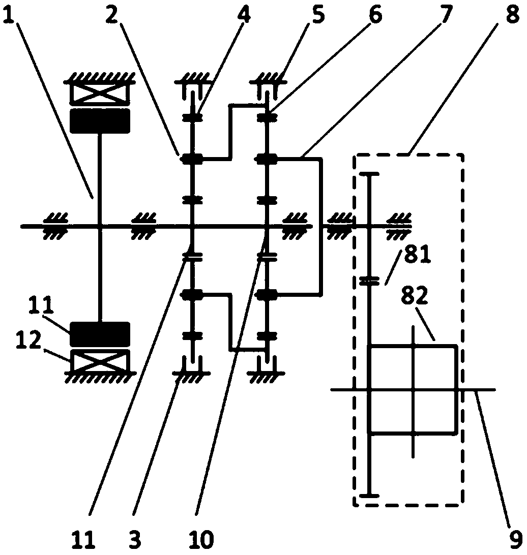
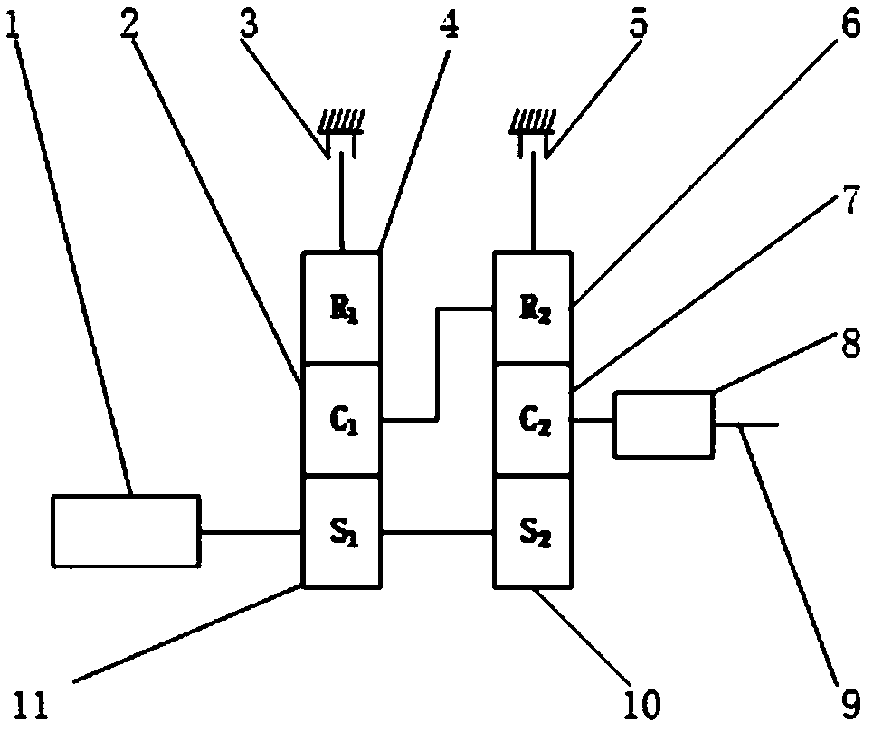
[0033] Such as figure 1 and figure 2 As shown, this embodiment provides an electric drive transmission for an electric vehicle, including: a first planetary gear set, a second planetary gear set, a drive motor 1, a first brake 3, a second brake 5, a differential Mechanism 8, PTO shaft 9 and housing. Wherein, the first planetary gear set includes a first planet carrier 2 , a first ring gear 4 and a first sun gear 11 . The second planetary gear set includes a second planet carrier 7 , a second ring gear 6 and a second sun gear 10 .

[0034] Specifically, the driving motor 1 , the f...


PUM


Abstract

The invention relates to an electric-driving transmission device for an electric vehicle and a control method. The electric-driving transmission device comprises a driving motor, a differential mechanism, a first brake, a second brake, a first planetary gear set and a second planetary gear set, wherein the first planetary gear set comprises a first sun wheel, a first planet carrier and a first gear ring, and the second planetary gear set comprises a second sun wheel, a second planet carrier and a second gear ring. An output shaft of a driving motor is sequentially connected with the first sunwheel and the second sun wheel. The first gear ring is connected with the first brake, and the second gear ring is connected with the second brake. The first planet carrier and the second gear ring are connected to form a whole, the second planet carrier is provided with an output support, and the output support is connected with an input shaft of the differential mechanism. Compared with the prior art, the electric-driving transmission device can achieve non power failure in the gear shifting process, is low in control complexity, has relatively low requirements for performance of the drivingmotor, and is high in practicability, compact in structure, small in size, low in weight and low in manufacturing cost.

Description

technical field [0001] The invention relates to the technical field of electric vehicle transmission, in particular to an electric drive transmission device and a control method for electric vehicles. Background technique [0002] At present, most of the pure electric vehicles on the market use a single-stage reduction mechanism without gears, and the motor completes the task of shifting. Although its structure is simple and the cost is low, it cannot take into account the power and economy of pure electric vehicles. According to the motor Characteristic curve, gearless deceleration is difficult to keep the drive motor working in the high-efficiency range, which reduces the efficiency of the electric drive assembly system. Especially in the low-load conditions of starting and maximum speed, the motor is in the low-efficiency zone, which seriously affects the life and endurance of the battery. [0003] In the patent with the publication number CN207333612U, a two-speed elect...

Claims


Application Information

Patent Timeline
Patent Type & Authority Applications(China)
IPC IPC(8): F16H37/08F16H57/10H02K7/116B60K17/16
CPCH02K7/116F16H37/0813F16H57/10B60K17/16F16H2200/0034F16H2200/2035F16H2200/2007B60K2001/001F16H3/66F16H2200/0021B60K1/00B60Y2400/73B60Y2200/91
Inventor 殷承良黄维黄建峰
Owner 上海屹驱新能源科技有限责任公司
Why Eureka
Try Eureka