Suspension tube structure for tube screen of boiler heating surface

A heating surface tube and suspension tube technology, which is applied in the field of boilers, can solve the problems of high precision of tube panel bending, limited welding space, and difficult assembly, etc., so as to save raw materials, reduce assembly difficulty, and reduce total weight. Effect

Pending Publication Date: 2018-12-28
哈尔滨哈锅锅炉容器工程有限责任公司
View PDF10 Cites 0 Cited by
  • Summary
  • Abstract
  • Description
  • Claims
  • Application Information

AI Technical Summary

Problems solved by technology

In the actual production process of this structure, because the suspension beam needs to be inserted into the gap between the two rows of tube panels, the precision of the tube panel bending is relatively high. In addition, due to the limited welding space, welding must be carried out every time a row of tube panels is passed through. When the number of tube panels is large, assembly is more difficult, especially when the last few rows of tube panels are installed, welding deformation, assembly tolerances, manufacturing tolerances and other unfavorable factors are superimposed, and assembly is extremely difficult, resulting in a longer assembly period

Method used


Image

  • Suspension tube structure for tube screen of boiler heating surface
  • Suspension tube structure for tube screen of boiler heating surface
  • Suspension tube structure for tube screen of boiler heating surface

Examples


specific Embodiment approach 1

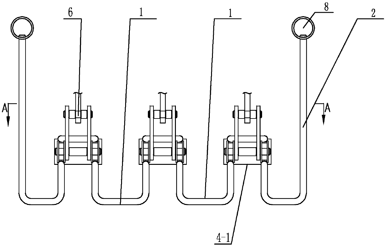
[0026] Specific implementation mode one: combine figure 1 Describe this embodiment, a boiler heating surface tube panel suspension tube structure in this embodiment includes a plurality of U-shaped tubes 1, two suspension tubes 2 and a plurality of suspension units, and a plurality of the suspension units are arranged side by side Two adjacent suspension units are connected by a U-shaped tube 1 , and the two suspension units located at both ends are respectively connected with two suspension tubes 2 . The number of suspension units can be increased or decreased according to the number of longitudinal tube panels.

specific Embodiment approach 2

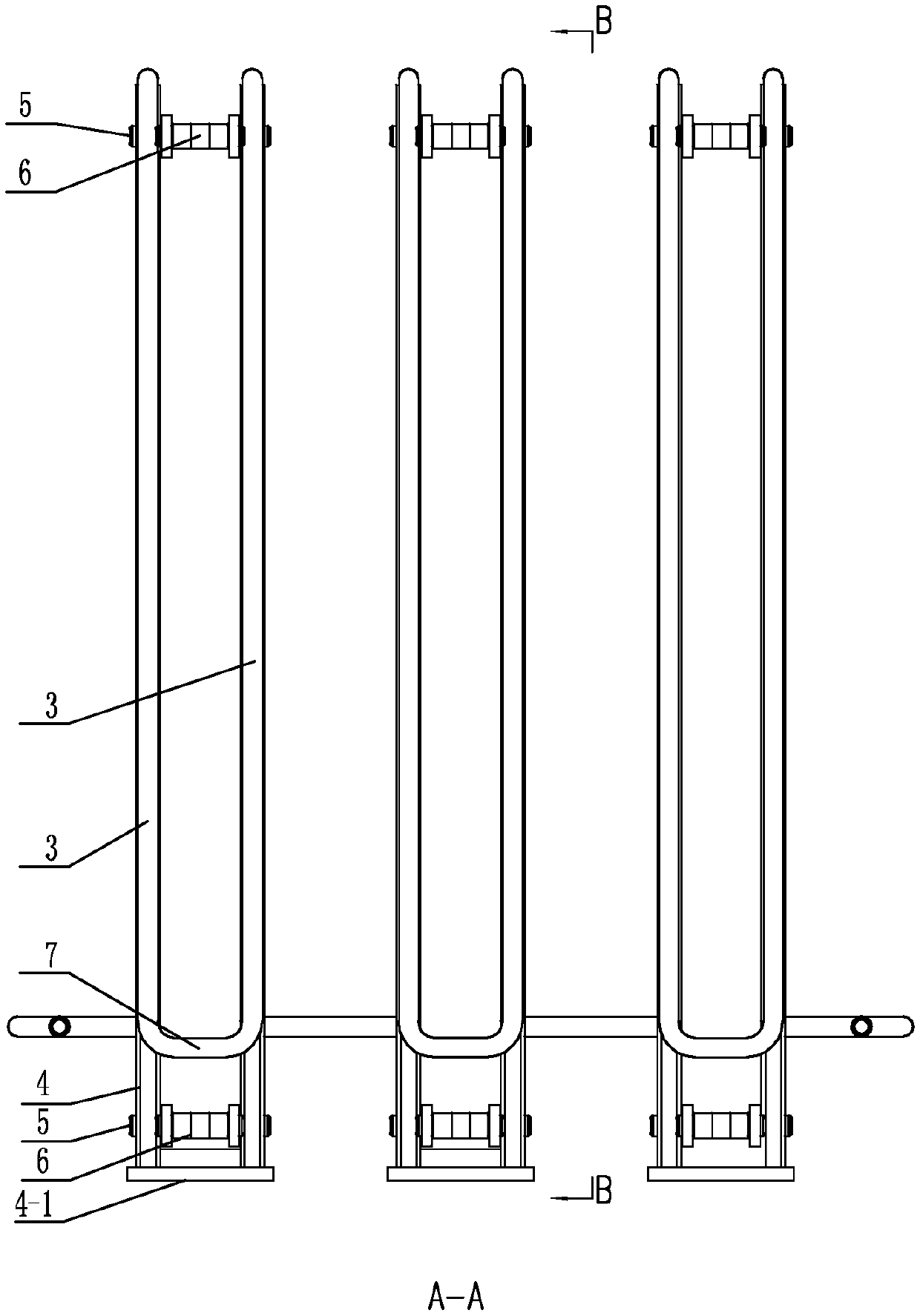
[0027] Specific implementation mode two: combination Figure 2 to Figure 3 Describe this embodiment, a boiler heating surface tube panel suspension pipe structure of this embodiment, each of the suspension units includes two U-shaped suspension pipes 3, two suspension pipe fixing devices 4, two pin shafts 5, The two hanging components 6 and the elbow 7, the two U-shaped hanging pipes 3 are respectively set on the two hanging pipe fixing devices 4, and the ends of the two U-shaped hanging pipes 3 located on the upper surface of the hanging pipe fixing device 4 pass through The elbow 7 is connected, and two pin shafts 5 are arranged side by side in parallel at the front and rear ends of the hanging pipe fixing device, and the two ends of each pin shaft 5 are connected with two hanging pipe fixing devices 4, and the hanging assembly 6 and the pin shaft 5 the middle connection. Other compositions and connections are the same as in the first embodiment.

[0028] The U-shaped hang...

specific Embodiment approach 3

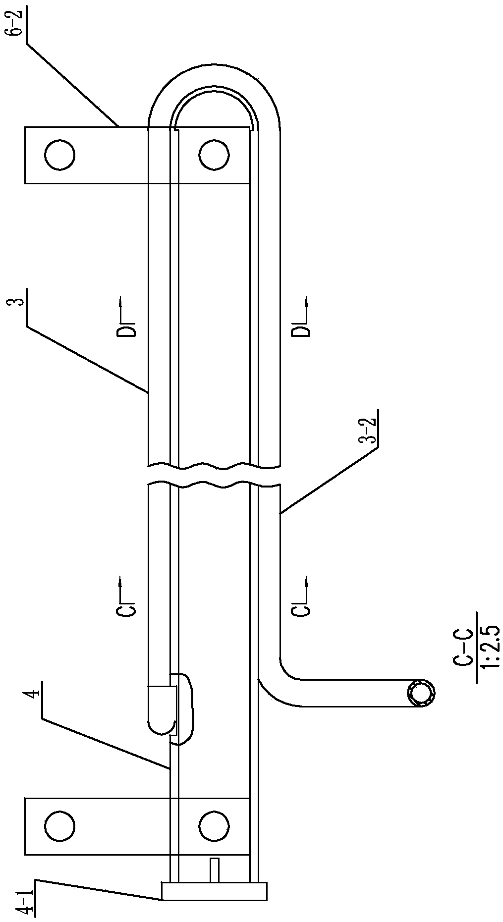
[0029] Specific implementation mode three: combination Figure 4 Describe the present embodiment, the hanging pipe fixing device 4 of the boiler heating surface tube panel hanging pipe structure of the present embodiment is a horizontal plate composed of an upper plate 4-1, a lower plate 4-2 and two side plates 4-3. A square tube with a rectangular cross section. This structure is used for fixing U-shaped hanging pipe 3 . Other compositions and connections are the same as those in the second embodiment.


PUM


Abstract

Provided is a suspension tube structure for a tube screen of a boiler heating surface. With a suspension tube to replace a suspension beam structure to not only play the role of a suspension beam butalso increase the area of heating surface, the suspension tube structure for the tube screen of the boiler heating surface provides improvement in two different directions, wherein one is to effectively increase the area of the heating surface and improve heat exchange rate with the overall structure and the number of tube screens not changed, and the other is to increase the heating area of the suspension tube and reduces the number of the tube screens passing through the suspension tube with the heat exchange rate of the heating surface not affected to greatly reduce the difficulty of assembly. The suspension tube structure for the tube screen of the boiler heating surface comprises multiple U-shaped tubes, two hanging tubes and multiple suspension units, wherein the multiple suspensionunits are arranged side by side, adjacent suspension units are connected through one U-shaped tube, and the two suspension units located on both ends are respectively connected with the two hanging tubes. The suspension tube structure for the tube screen of the boiler heating surface is applied to the technical field of boilers.

Description

technical field [0001] The invention relates to a suspension tube structure, in particular to a tube panel suspension tube structure on a heating surface of a boiler. The invention belongs to the technical field of boilers. Background technique [0002] The tube panel on the heating surface of the boiler uses the heat of the high-temperature flue gas to heat the working medium in the tube panel, thereby reducing the exhaust gas temperature and increasing the combined cycle rate of the boiler to achieve the purpose of energy saving and environmental protection. Therefore, the heat transfer rate of the tube panel on the heating surface of the boiler plays a vital role in the operation of the boiler. [0003] See the accompanying drawings in the manual Figure 7 to Figure 12 Most of the suspension structure of the existing tube panels on the heating surface of the boiler adopts the form of square steel penetrating the tube panel, and the tube panel is fixed by the cooperation o...

Claims


Application Information

Patent Timeline
Patent Type & Authority Applications(China)
IPC IPC(8): F22B37/24F24H9/06
CPCF22B37/24F24H9/06
Inventor 贺宏宇付鹤孙军陈建宇梁喜佳
Owner 哈尔滨哈锅锅炉容器工程有限责任公司
Why Eureka
Try Eureka