Test bench for measuring overall performance of high-speed electric main shaft

A high-speed electric spindle and comprehensive performance technology, which is applied in the testing of mechanical components, testing of machine/structural components, measuring devices, etc., can solve problems such as inaccurate applied force, large influence of structure and parameters, and increased error , to achieve the effect of simple structure and accurate applied force

Inactive Publication Date: 2018-12-28
HARBIN UNIV OF SCI & TECH
View PDF13 Cites 3 Cited by
  • Summary
  • Abstract
  • Description
  • Claims
  • Application Information

AI Technical Summary

Problems solved by technology

Most of the existing electric spindle comprehensive performance test benches are mainly empty-loaded, and a few test benches can apply radial force, axial force, and tangential force, but the two ends of the measuring shaft are fixed, and the force is applied at the middle position, which cannot simulate the electric spindle. In the cantilever state where the spindle is working with a tool, the applied force is inaccurate, resulting in inaccurate experimental data, which has a great impact on the improvement and optimization of the structure and parameters of the high-speed electric spindle. The contact of the electric spindle affects the measurement accuracy and increases the error

Method used


Image

  • Test bench for measuring overall performance of high-speed electric main shaft
  • Test bench for measuring overall performance of high-speed electric main shaft
  • Test bench for measuring overall performance of high-speed electric main shaft

Examples


Embodiment Construction

[0021] The specific embodiment of the present invention will be further described below in conjunction with accompanying drawing:

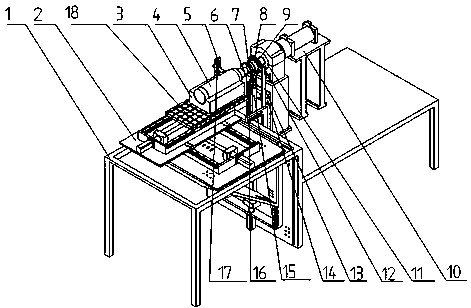
[0022] Such as figure 1 As shown, the test bench for the comprehensive performance of the high-speed electric spindle is characterized in that: a mobile platform 2 is installed on the left side of the test bench 1, a ground plate 18 is installed on the mobile platform 2, and a replaceable electric motor is installed on the ground plate 18. The spindle clamping structure 3, the electric spindle 4 to be tested is installed on the replaceable electric spindle clamping structure 3, the electric spindle 4 to be tested is connected to the docking shaft 6 through a broaching device, and the docking shaft 6 It is connected with the coupling 7, the coupling 7 is connected with the experimental shaft 8, the speed plate 9 is installed at the spline position of the experimental shaft 8, and the right side of the experimental shaft 8 is connected with the tang...


PUM


Abstract

The invention discloses a test bench for measuring the overall performance of a high-speed electric main shaft, and belongs to the field of the performance measurement of the electric main shaft. An experiment table is connected with a mobile platform, the mobile platform is provided with a replaceable electric main shaft clamping structure, a tested electric main shaft is installed on the electric main shaft clamping structure, the mobile platform realizes automatic butt joint with a right side butt joint shaft through the synthetic function of a system and a sensor, the experiment table is provided with a laser vibration sensor, an infrared temperature sensor and a revolving speed sensor, the butt joint shaft is connected with an experiment shaft through a coupler, the experiment shaft is connected with a resolving speed disk through a spline, and the right end of the experiment shaft is connected with a magnetic powder brake; the magnetic powder brake is installed above a radial force mechanism; and an axial force mechanism is installed on the right side of the magnetic powder brake to simulate external force borne when the electric main shaft works. By use of the test bench, the problems that an existing test bench is difficult to simulate a real stress condition, the sensor is not in contact with a tested object and influences and errors are lowered are solved, and a radial force top plate and an axial force top plate are independently provided with a pressure sensor to form closed loop control. The test bench is used for measuring the overall performance of the high-speed electric main shaft.

Description

technical field [0001] The invention relates to a test bench for measuring the comprehensive performance of a high-speed electric spindle, which belongs to the field of performance measurement of a high-speed electric spindle. Background technique [0002] High-speed electric spindles are widely used in the field of CNC machining centers, and are used in the processing of various parts, which improves the existing processing accuracy and processing efficiency. However, in order to ensure the machining accuracy and stability of the high-speed electric spindle, it is necessary to conduct simulation experiments on the high-speed electric spindle to improve and optimize the structure and parameters of the high-speed electric spindle. Most of the existing electric spindle comprehensive performance test benches are mainly empty-loaded, and a few test benches can apply radial force, axial force, and tangential force, but the two ends of the measuring shaft are fixed, and the force ...

Claims


Application Information

Patent Timeline
Patent Type & Authority Applications(China)
IPC IPC(8): G01M13/00
CPCG01M13/00
Inventor 张元王丽锋张津
Owner HARBIN UNIV OF SCI & TECH
Why Eureka
Try Eureka