
Automatic argon arc welding equipment for liquid storage tank

A technology of argon arc welding and liquid storage tank, which is applied in welding equipment, welding equipment, arc welding equipment, etc., can solve the problems of low production efficiency and low degree of automation, and achieves the improvement of welding quality, transmission efficiency and rigidity. Effect

Pending Publication Date: 2019-01-01
FOSHAN GOOGOL AUTOMATION TECH
View PDF0 Cites 6 Cited by
  • Summary
  • Abstract
  • Description
  • Claims
  • Application Information

AI Technical Summary

Problems solved by technology

At the same time, the automatic welding equipment solves the problems of low automation and low production efficiency in the current welding industry while ensuring the welding quality of the liquid storage tank, and is suitable for large-scale production of intelligent manufacturing of liquid storage tanks

Method used


Image

  • Automatic argon arc welding equipment for liquid storage tank
  • Automatic argon arc welding equipment for liquid storage tank
  • Automatic argon arc welding equipment for liquid storage tank

Examples


Embodiment 1

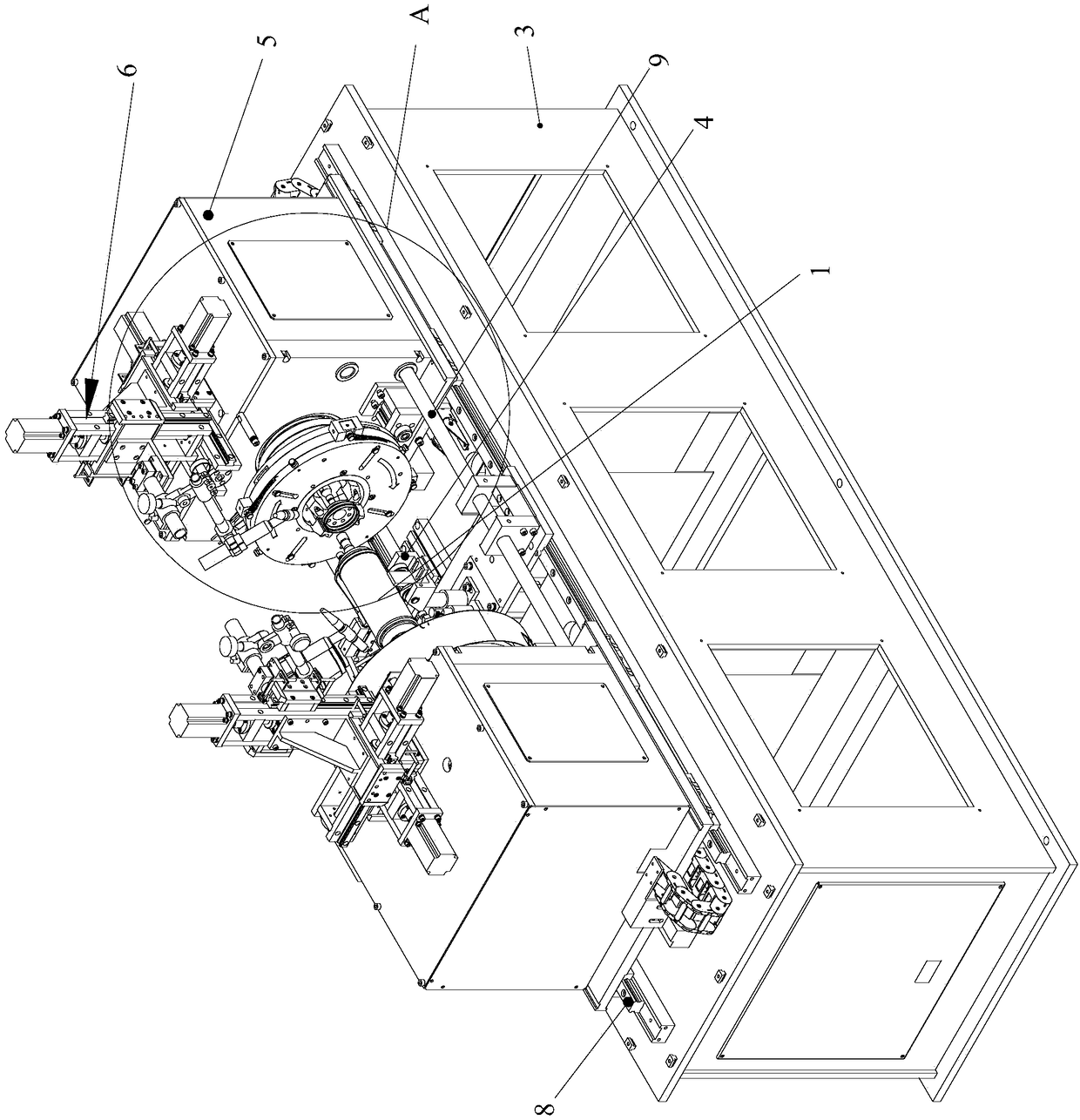
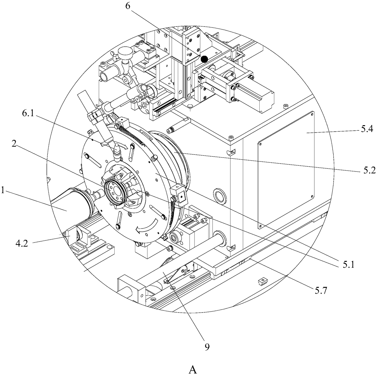
[0062] Such as Figure 1 to Figure 9 As shown, an automatic argon arc welding equipment for a liquid storage tank according to the present invention is used for positioning and welding the liquid storage tank body 1 and two end caps 2; including:

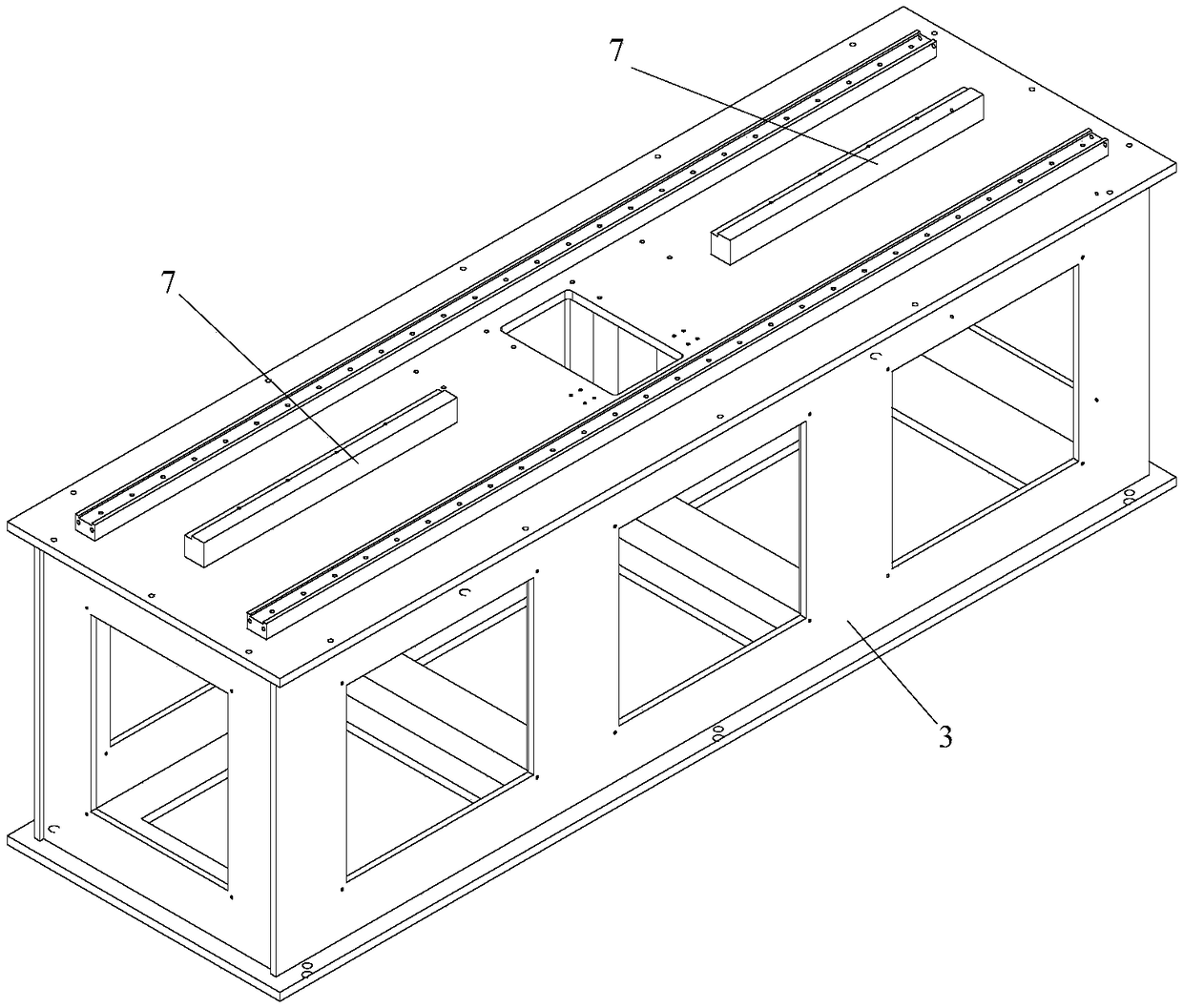
[0063] Rack 3;

[0064] The clamping and rotating mechanism for positioning the liquid storage tank body 1 and the two end caps 2, the clamping and rotating mechanism includes a holding device 4 for holding the liquid storage tank body 1 and for clamping the end caps 2 and A dual-spindle clamping device that can drive the end cover 2 to rotate;

[0065] Linear traveling device for linear movement of dual-spindle clamping device;

[0066] A welding device 6 for welding the liquid storage tank body 1 and the end cover 2;

[0067] Gas protection device for cooling and anti-oxidation during welding;

[0068] Among them, the linear walking device is arranged on the frame 3, the double-spindle clamping device is two spindle bases 5 wi...

Embodiment 2

[0080] The only difference between this embodiment and the implementation one is that: Figure 10 As shown, the clamp is a cylindrical sleeve 17, and the sleeve 17 is matched with the end cap. The set 17 can be matched and fixed with the end cap by adopting an existing structure. For example, a clip for engaging and fixing with the end cap can be provided at the end of the set, and the clip can be engaged and fixed with the end cap.

[0081] Other structures of this embodiment are consistent with Embodiment 1.


PUM


Abstract

The invention provides automatic argon arc welding equipment for a liquid storage tank. The automatic argon arc welding equipment for the liquid storage tank comprises a machine frame, a supporting device, a double-spindle clamping device, a straight line walking device, welding devices and a gas protecting device. The straight line walking device is arranged on the machine frame, the double-spindle clamping device is two spindle seats with clamps, wherein the two spindle seats are arranged opposite to each other on the same horizontal axis, and the two welding devices are separately connectedwith the two spindle seats and arranged above the two spindle seats. The supporting device is arranged in the middle of the two spindle seats. The two spindle seats walk and move towards each other through the straight line walking device, end covers clamped on both sides move along the same horizontal axis to both ends of a liquid storage tank body of the supporting device, and the liquid storage tank body and the end covers are positioned and rotated on a welding station. The gas protecting device is arranged in one of the spindle seats, the gas outlet end of the gas protecting device communicates with the inner portions of the clamped end covers, and ventilation cooling and oxidation prevention during welding are realized. According to the automatic argon arc welding equipment for theliquid storage tank body, fast and reliable automatic welding between the liquid storage tank body and the end covers can be realized.

Description

technical field [0001] The invention relates to the technical field of welding processing, and more specifically relates to an automatic argon arc welding equipment for a liquid storage tank. Background technique [0002] As an important part of the air conditioning system, the liquid storage tank is used at the suction end of the compressor. Its function is to suck in the refrigerant that has passed through the refrigeration cycle of the air conditioner, filter it, and then transport it to the compression chamber of the compressor for the next round of refrigeration cycle. . The refrigerant will condense into small droplets under the influence of the surrounding low-temperature environment. Therefore, the impurities are filtered through the liquid storage tank, and at the same time, the oil droplets and refrigerant droplets are atomized and then enter the refrigeration cycle, which can prevent impurities from entering the compressor and solve the problem of jamming. Proble...

Claims


Application Information

Patent Timeline
Patent Type & Authority Applications(China)
IPC IPC(8): B23K9/127B23K9/167B23K37/047B23K37/053
CPCB23K9/127B23K9/167B23K37/047B23K37/053
Inventor 胡国强
Owner FOSHAN GOOGOL AUTOMATION TECH
Learn More