
A Pointer Type Chip Positioning Fixture

A positioning fixture and pointer-type technology, applied in the field of positioning fixtures, can solve the problem that the fixture cannot meet the needs of process processing, and achieve the effect of simple and feasible operation process, small space occupation and large adjustable range

Active Publication Date: 2020-04-14
CHONGQING UNIVERSITY OF SCIENCE AND TECHNOLOGY
View PDF5 Cites 0 Cited by
  • Summary
  • Abstract
  • Description
  • Claims
  • Application Information

AI Technical Summary

Problems solved by technology

[0005] The main purpose of the present invention is to provide a multifunctional biological chip positioning jig with simple operation to solve the problem that the jigs in the prior art cannot meet the needs of process processing

Method used


Image

  • A Pointer Type Chip Positioning Fixture
  • A Pointer Type Chip Positioning Fixture
  • A Pointer Type Chip Positioning Fixture

Examples


Embodiment Construction

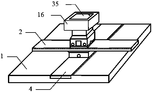
[0027] refer to Figure 1-Figure 12 The shape structure in the middle is a pointer type chip positioning fixture, which is composed of a main body and a sample stage 16. It is characterized in that: the bottom of the main body is a cuboid base 1 whose top surface is square or rectangular. A longitudinal rail 4 across the front and back is installed in the middle of the upper surface, and the two ends of the longitudinal rail 4 are flush with the fixture base 1 . Above the longitudinal track 4 is the lower electric slider 13 matched with it. A precision track motor is installed inside the lower electric slider 13. On the pallet 12 at the top of the lower electric slider 13, a The horizontal track 2. Above the transverse track 2 is an upper electric slide block 8 that cooperates with it, and a precision track motor is installed inside the upper electric slide block 8, and a hydraulic device 6 is installed on its top. On the top surface of the lifting column 7 inside the hydrau...


PUM


Abstract

The invention provides a pointer type chip positioning fixture. A longitudinal track and a transverse track are used for controlling the position of the fixture, and then the position of a sample table carrying a biological chip on the horizontal plane is determined. The height is controlled by a hydraulic device, and then the position of the sample table carrying the biochip in the vertical direction is determined. The pointer type chip positioning fixture has the technical characteristics that the designed pointer type sample table serves as an objective table of the fixed chip, and the position of a pointer base is moved, so that a transverse pointer and a longitudinal pointer clamp the chip, the positioning fixture can be also suitable for the chips with different shapes, and the fixing position of the to-be-processed chip is more accurate. The whole fixture is simple and feasible in operation process, the chip can be fixed, and also the chip can be positioned, the processing efficiency is improved, and the quality is improved.

Description

technical field [0001] The invention relates to a positioning jig. Simply put, it is a pointer-type chip positioning jig used for laser engraving machines that can fix biochips of different shapes and sizes and determine their positions. [0002] technical background [0003] At present, with the rapid development of society, lithography technology, as a key technology of microfabrication, is widely used in microfabrication fields such as biochips. At this stage, many lithography machines are not equipped with fixing fixtures, let alone fixtures for fixing biochips, so that the substrate of the biochip cannot be fixed, and the substrate of the biochip may be accidentally touched during the operation, which will cause Change the position of lithography, or even cause lithography failure and re-operation, affecting processing time, efficiency, and quality. Secondly, some biochips need not only photolithography once, but also multiple photolithography, and each time the photoli...

Claims


Application Information

Patent Timeline
Patent Type & Authority Patents(China)
IPC IPC(8): B23K26/362B23K26/70
CPCB23K26/361B23K26/362B23K26/702
Inventor 徐文峰廖晓玲徐紫宸
Owner CHONGQING UNIVERSITY OF SCIENCE AND TECHNOLOGY
Learn More