
Automatic COF coil punching device

A technology of automatic punching and punching dies, which is applied in the field of automatic punching equipment for COF coils, can solve the problems of no punching equipment, etc., achieve the effect of improving work efficiency and automation, reducing the rate of defective products in production, and improving the yield rate

Inactive Publication Date: 2019-01-01
浙江鼎晶科技有限公司
View PDF6 Cites 4 Cited by
  • Summary
  • Abstract
  • Description
  • Claims
  • Application Information

AI Technical Summary

Problems solved by technology

[0003] COF coil production does not separate individual COFs, and there is no punching equipment on the existing market

Method used


Image

  • Automatic COF coil punching device
  • Automatic COF coil punching device
  • Automatic COF coil punching device

Examples


Embodiment 1

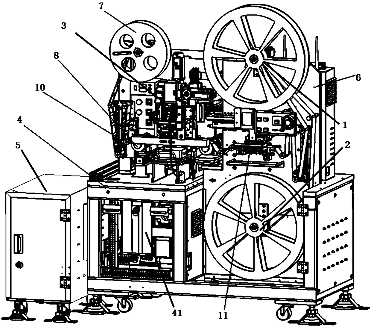
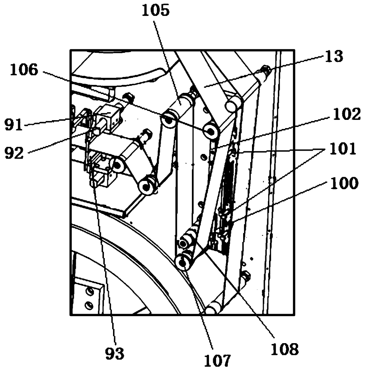
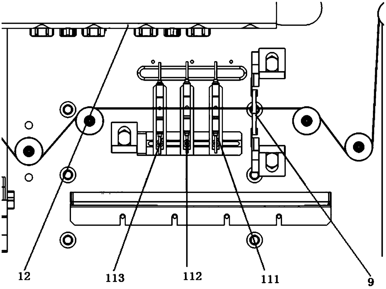
[0024] see Figure 1 to Figure 6 , the COF coil material automatic punching device in the present embodiment, comprises COF strip 13, frame 6, cabinet 4 and UPS uninterruptible power supply 5, is characterized in that: also comprises new material wheel 1, protective film recovery wheel 2, Waste recycling wheel 7, ratchet 8, punching mechanism 3 and a plurality of guide wheels; upper frame 6 and cabinet 4 are connected to form a device body, UPS uninterruptible power supply 5 forms a circuit connection with the electrical cabinet 41 inside the device body from the outside, The waste recovery wheel 7 and the new material wheel 1 are arranged on the top of the device body successively, and the protective film recovery wheel 2 is arranged on the bottom of the device body and corresponds to the new material wheel 1. The new material wheel 1, the protective film recovery wheel 2 and The rotating shaft in the middle part of the scrap recovery wheel 7 is connected with the servo motor...


PUM


Abstract

The invention provides an automatic COF coil punching device. The automatic COF coil punching device comprises a COF material strip, a rack, a cabinet and a UPS, and is characterized by further comprising a new material wheel, a protective film recycling wheel, a waste recycling wheel, ratchet wheels, a punching mechanism and a plurality of guide wheels, wherein the two ratchet wheels are vertically arranged on the portion, between the new feeding wheel and the protective film recycling wheel, of the rack; the punching mechanism is arranged between the two ratchet wheels; the punching mechanism comprises a mounting block, a Z-direction servo motor, a screw rod, a horizontal correction block, a finished product box and a punching die; the mounting block is vertically arranged on the rack; the Z-direction servo motor is vertically arranged on the mounting block; one end of the screw rod is connected with the output end of the Z-direction servo motor; the other end of the screw rod penetrates through a supporting block of the punching die; the other end of the screw rod and the supporting block of the punching die form a screw rod transmission structure; the horizontal correction block is horizontally connected to the rack and is rectangular; the punching die penetrates through the horizontal correction block and can move in the vertical direction through the screw rod transmission structure; and the finished product box is arranged below the punching die.

Description

technical field [0001] The invention relates to the field of LCM liquid crystal module production equipment, in particular to a COF roll material automatic punching device. Background technique [0002] In the production process of LCM liquid crystal module, the traditional production process is to bind IC (integrated circuit) to GLASS (liquid crystal screen), and then bind FPC (flexible circuit board) to GLASS (liquid crystal screen), the process is complicated, And the screen-to-body ratio does not meet the current market demand. The COF roll material directly integrates the IC (integrated circuit) and FPC (flexible circuit board), and the position of the IC (integrated circuit) is directly bound to the FPC (flexible circuit board), and the original IC position can be canceled, thereby realizing a full screen craft. [0003] COF coil production does not separate individual COFs, and there is no punching equipment on the existing market. In response to the current new CO...

Claims


Application Information

Patent Timeline
IPC IPC(8): B26F1/40B26D7/14B26D7/27B08B1/02B08B5/02
CPCB08B5/02B26D7/14B26D7/27B26F1/40B08B1/20B08B1/12
Inventor 余雄喻泷
Owner 浙江鼎晶科技有限公司
Learn More