Device for simulating tsunami/gravity flow under super-gravity field

A technology of generating device and supergravity field, which is applied in teaching models, educational appliances, instruments, etc., can solve the problems of incapable of gravity flow at the bottom of the liquid storage tank, large gap between tsunami waves and tsunami waves, simulation, etc., to achieve sufficient control power, Reduced resistance and precise control

Pending Publication Date: 2019-01-01
GENERAL ENG RES INST CHINA ACAD OF ENG PHYSICS
View PDF11 Cites 2 Cited by
  • Summary
  • Abstract
  • Description
  • Claims
  • Application Information

AI Technical Summary

Problems solved by technology

Therefore, the tsunami wave formed by the gate opening method is quite different from the actual tsunami wave, and lacks the guiding significance for actual engineering
[0005] In addition, the deep-sea gravity flow simulation generation device and the tsunami simulation generation device have a high similarity in model boxes, water supply, and generation devices, and there is a possibility of integration and sharing
The hydraulic cylinder is placed at the bottom of the liquid storage tank to pull the gate horizontally, so that after the gate is opened, the liquid at the bottom of the liquid storage tank cannot participate in the tsunami simulation, resulting in the waste of some liquid and making it impossible to store liquid The simulation of gravity flow at the bottom of the tank does not have the function of deep sea gravity flow simulation

Method used


Image

  • Device for simulating tsunami/gravity flow under super-gravity field
  • Device for simulating tsunami/gravity flow under super-gravity field
  • Device for simulating tsunami/gravity flow under super-gravity field

Examples


Embodiment 1

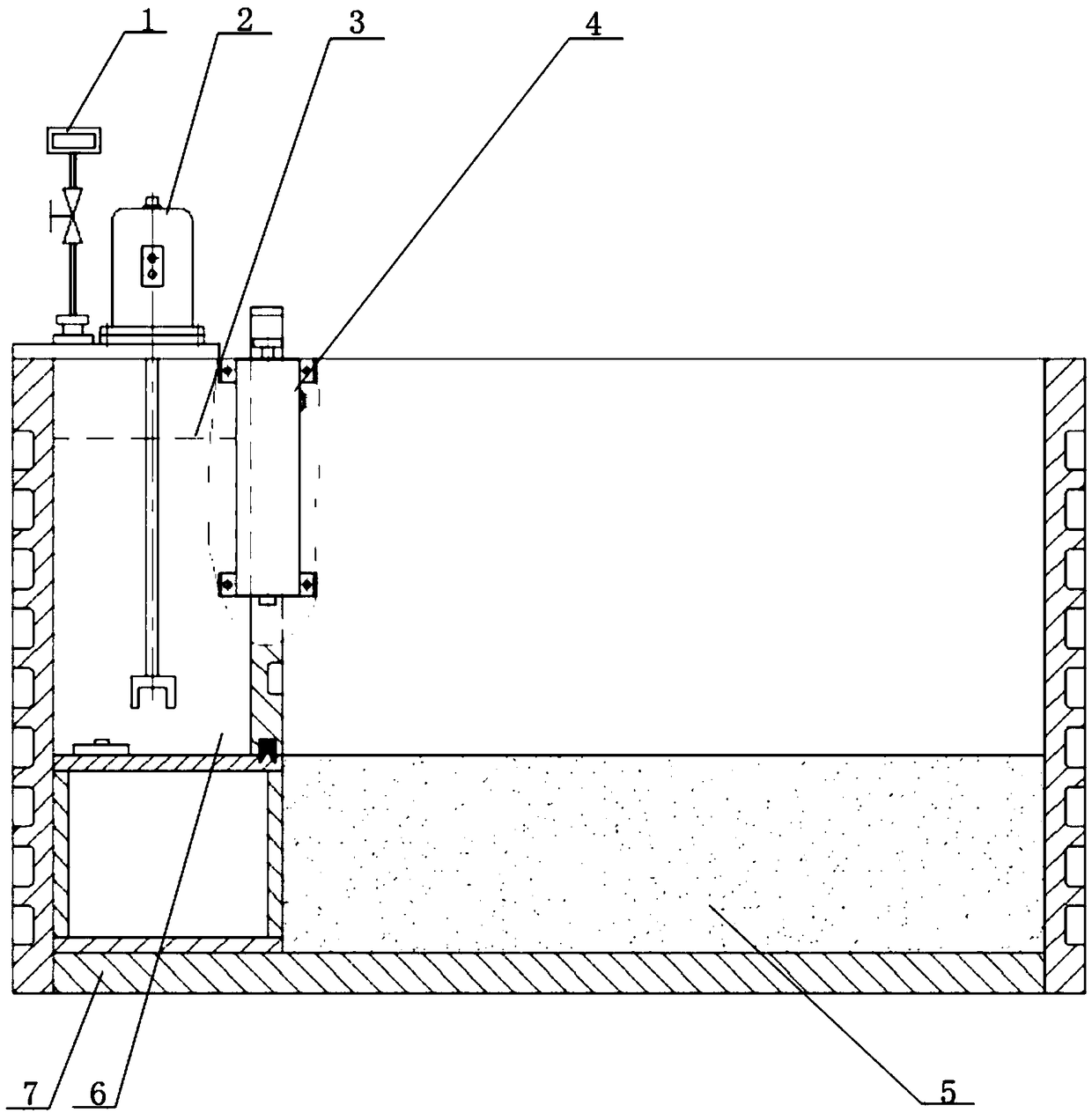
[0042] Example 1, such as figure 1 and Figure 6 Shown:

[0043] The tsunami / gravity flow simulation generating device under the supergravity field is installed in the centrifuge basket, and the tsunami / gravity flow simulation generating device includes:

[0044] The model box 7; the soil body 5 is set at the bottom of the model box 7;

[0045] The tsunami / gravity flow simulation generator also includes:

[0046] Liquid storage tank 6; the liquid storage tank 6 is arranged at one end inside the model box 7, and the water or gravity flow medium 3 is stored inside the liquid storage tank 6, and the lowermost end of the water or gravity flow medium 3 in the liquid storage tank 6 is in contact with the soil body 5 The surfaces of are in the same plane;

[0047] The gate rapid lifting unit 4 for discharging the water or gravity flow medium 3 in the liquid storage tank 6 from above the upper surface of the soil body 5 to the upper part of the soil body 5; the gate rapid lifting ...

Embodiment 2

[0050] Example 2, such as Figure 6 as shown,

[0051] The difference between this embodiment and Embodiment 1 is that the power mechanism includes a plurality of hydraulic cylinders 42 components, and the hydraulic cylinders 42 components include a hydraulic cylinder 42, a servo valve 43, an accumulator 44, and a laser displacement sensor for measuring the displacement of the hydraulic cylinder 42 , the first control system, the piston rods of a plurality of hydraulic cylinders 42 respectively act on the top of the gate 41 and are used to lift and lower the gate 41, the data signal output end of the laser displacement sensor is connected with the data signal input end of the first control system, the second The control signal output end of a control system is connected with the control signal input end of the servo valve 43, and the hydraulic cylinder 42, the servo valve 43, and the ground oil source form a basic hydraulic basic working circuit through pipelines (this is the ...

Embodiment 3

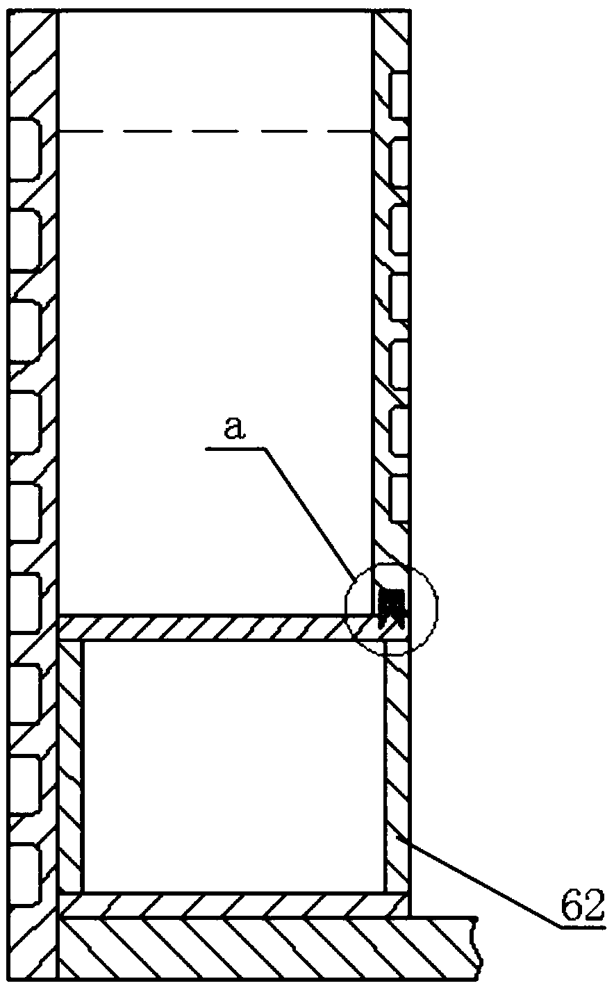
[0054] Example 3, such as figure 2 , image 3 , Figure 4 , Figure 5 as shown,

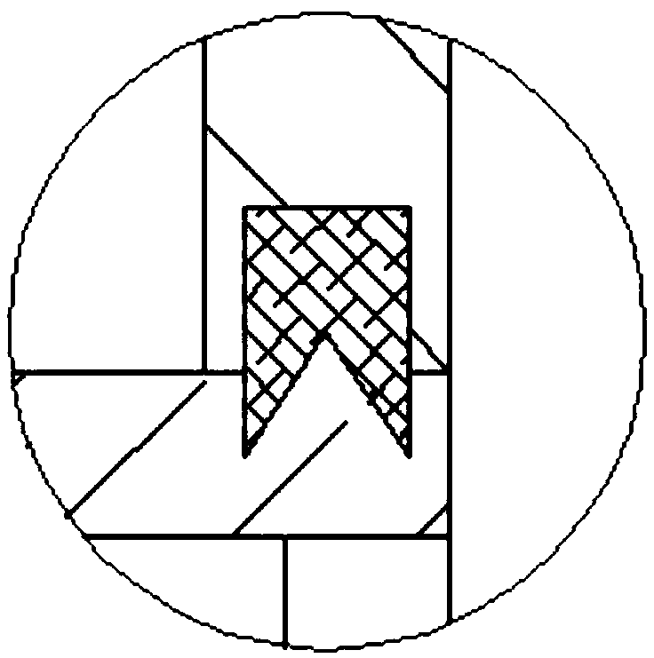
[0055] The difference between this embodiment and Embodiment 1 is that P-type water-stop rubber is used for bidirectional sealing between the gate 41 and the walls of the model box 7 on both sides, and a wedge-shaped rubber plate is used for bidirectional sealing between the bottom of the gate 41 and the liquid storage tank 6 .

[0056] The adoption of the P-type water-stop rubber and the wedge-shaped rubber plate can minimize the resistance to the opening of the gate 41 by the friction generated by the seal while ensuring that the liquid in the liquid storage tank 6 does not leak before the gate 41 is opened.

[0057] Two P-type water-stop rubbers are respectively placed on both sides of one end of the gate to form a side sealing structure 45 .

[0058] In this embodiment, in order to cooperate with the stable installation and connection of the P-type water-stop rubber and the wedge-shaped ...


PUM


Abstract

The invention discloses a device for simulating a tsunami / gravity flow under a super-gravity field. According to the device, a gate quick lifting unit, a model box and a liquid storage tank are combined to simulate the generation of a tsunami and deep sea gravity flow under a super-gravity environment. According to the device, tsunami and gravity flow simulation is unobstructed, smoother and quicker; all liquid in the liquid storage tank of the device can participate in tsunami simulation; the liquid storage tank of the device can provide space for the storage and stirring of mud when realizing the simulated occurrence of the tsunami, and therefore, the simulation of the deep sea gravity flow is realized, and the function and use scope of the device can be expanded; a stirring unit is mainly used to a seabed gravity flow simulation experiment; before the seabed gravity flow simulation experiment is started, the mud in the liquid storage tank is continuously stirred through the stirringunit, and therefore, the uniformity of the mud can be ensured, the precipitation or agglomeration of the mud can be avoided; and thus, the device of the invention can better simulate the gravity flow.

Description

technical field [0001] The invention belongs to the technical field of tsunami / gravity flow simulation generation, and in particular relates to a tsunami / gravity flow simulation generation device under a supergravity field. Background technique [0002] The tsunami simulation generating device in the supergravity field is based on the scaling effect to simulate the physical environment of marine disasters such as tsunamis and deep-sea gravity currents in the super-gravity field environment, in order to reveal and study the damage process and Mechanism and explore the corresponding disaster prevention and control technology to provide an experimental platform. [0003] The tsunami simulation generating device in the hypergravity field has only been built by individual scientific research institutions. Japan’s Kyoto University has a tsunami simulation experiment device, which uses a hydraulic cylinder to pull the gate at the bottom of the liquid storage tank to move horizonta...

Claims


Application Information

Patent Timeline
Patent Type & Authority Applications(China)
IPC IPC(8): G09B23/00
CPCG09B23/00
Inventor 王鑫磊李心耀尹娇妹黎启胜宋琼李明海尹鹏
Owner GENERAL ENG RES INST CHINA ACAD OF ENG PHYSICS
Why Eureka
Try Eureka