Display device with dynamic adjustment of transparent backlight

A technology of dynamic adjustment and display device, which is applied in the direction of static indicators, optics, nonlinear optics, etc. It can solve the problems of human visual fatigue, unclear picture contrast, flickering brightness of display screen, etc., and achieve UV protection , easy to visual fatigue, anti-bird stone impact effect

Pending Publication Date: 2019-01-01
JIANGSU IRON ANCHOR GLASS LTD BY SHARE LTD
View PDF6 Cites 5 Cited by
  • Summary
  • Abstract
  • Description
  • Claims
  • Application Information

AI Technical Summary

Problems solved by technology

[0003] However, since the transparent displays used in liquid crystal display (LCD) transparent display technology and organic light-emitting diode (OLED) transparent display technology have a certain degree of light penetration, the background on the back side of the transparent display will interfere with the picture displayed by the transparent display, for example When the pattern of the background on the back side overlaps with the picture displayed on the transparent display or presents a similar color, it is easy to cause the problem of unclear and low contrast of the picture displayed on the transparent display, and it will also cause visual fatigue of the human eye, etc. Negative impact
[0004] In addition, the liquid crystal display (LCD) transparent display technology relies on the background light as the display backlight. In some scenes such as cars or high-speed rail, the intensity of the background light varies with time and place, causing the brightness of the display screen to flicker, resulting in poor image quality. Problems with poor experience

Method used


Image

  • Display device with dynamic adjustment of transparent backlight
  • Display device with dynamic adjustment of transparent backlight
  • Display device with dynamic adjustment of transparent backlight

Examples


Embodiment 1

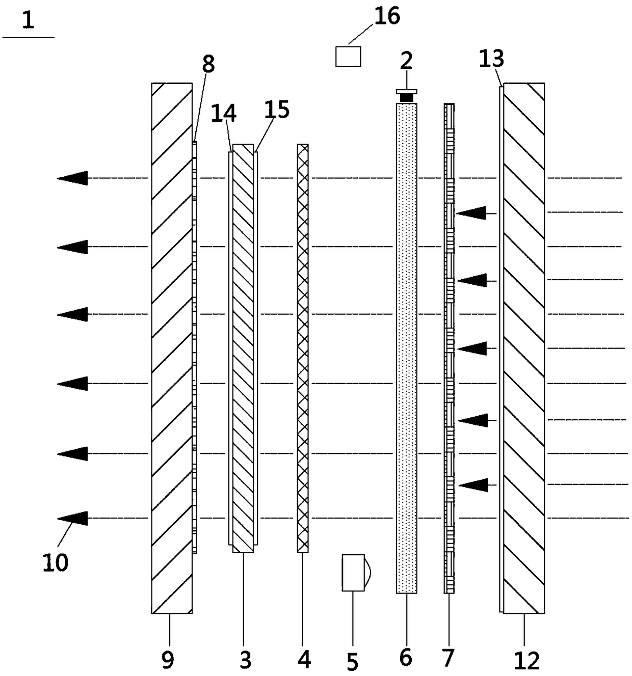
[0051] Please refer to figure 1 As shown, under the condition of strong ambient light source illumination: the electronic control unit 16 controls the ambient brightness module acquisition layer 5 to power on, the brightness value acquired by the ambient brightness module acquisition layer 5 is greater than the preset range, and the ambient brightness module acquisition layer 5 sends the second signal to control the electronic control unit 16 to stop powering the light-emitting diode 2, so that the light-emitting diode 2 stops emitting the light source 11; The transmittance of the film layer 7 can intercept and absorb all unnecessary light rays, and then adjust the brightness of the ambient light source 10 irradiating the thin film transistor liquid crystal display layer 3 .

[0052] At this time, if the electronic control unit 16 controls the touch panel layer 8, the inner protective glass 9, the thin film transistor liquid crystal display layer 3, the liquid crystal layer 4 ...

Embodiment 2

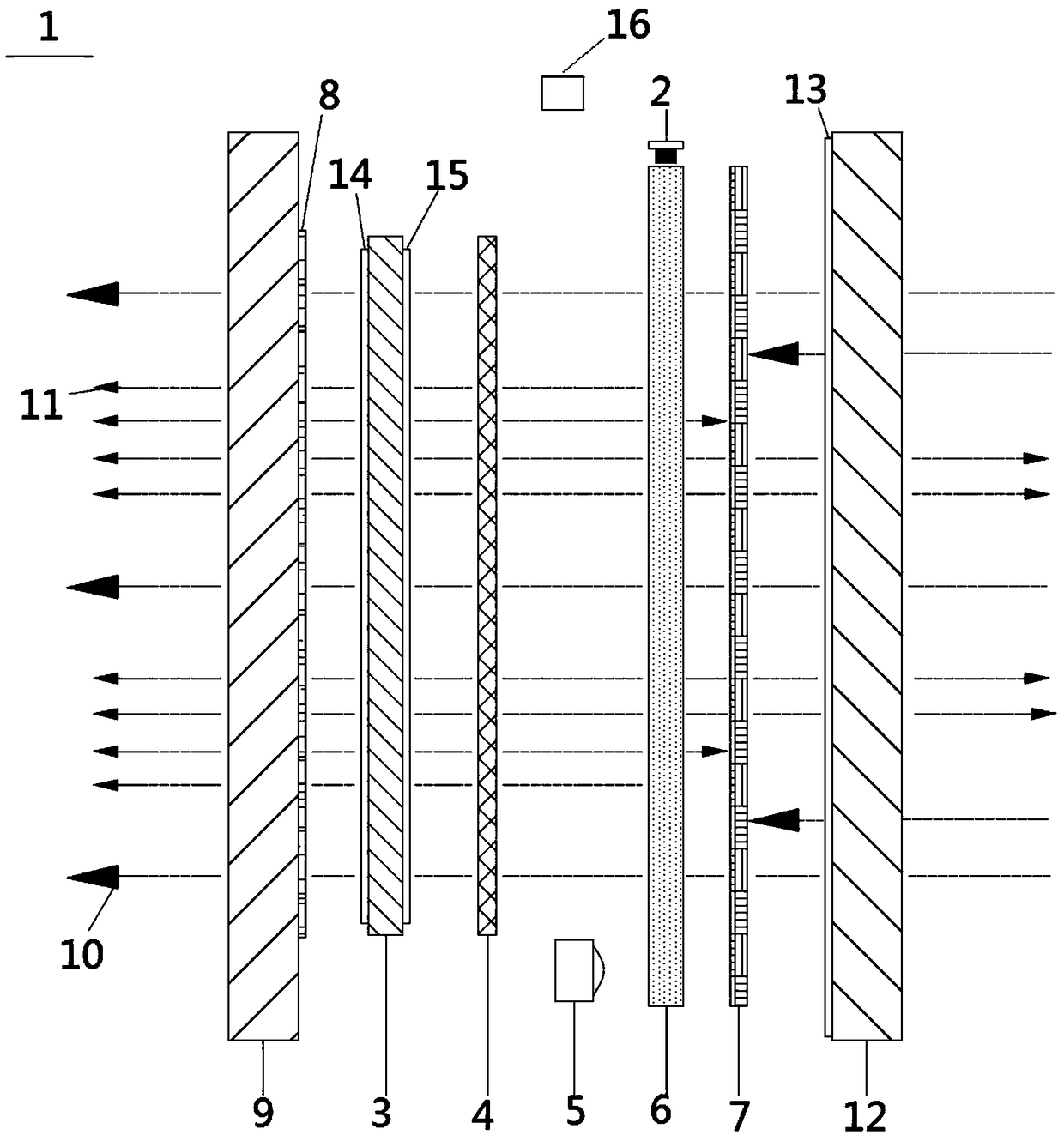
[0057] Please refer to figure 2 As shown, under the condition of weak ambient light source illumination: the electronic control unit 16 controls the ambient brightness module acquisition layer 5 to power on, and when the brightness value obtained by the ambient brightness module acquisition layer 5 is less than the preset range and greater than the preset value, the ambient brightness module The acquisition layer 5 sends the first signal to control the electronic control unit 16 to power the light emitting diode 2 and the light guide plate layer 6, so that the light emitting diode 2 emits the light source 11 through the light guide plate layer 6, and the electronic control unit 16 adjusts the magnitude of the current to control The intensity of the light source 11 emitted by the light emitting diode 2 is used to adjust the brightness of the light source 11 emitted by the light emitting diode 2 on the thin film transistor liquid crystal display layer 3 , so that the brightness ...

Embodiment 3

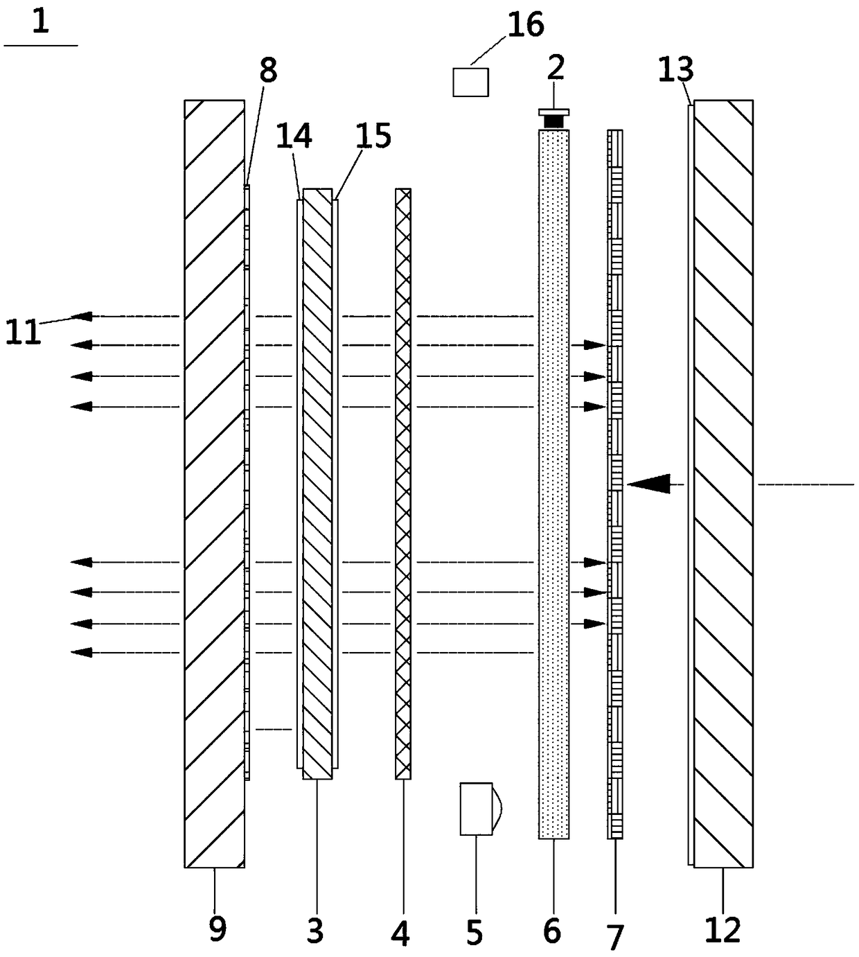
[0063] Please refer to image 3 As shown, under the condition of weak or no illumination of the ambient light source: the electronic control unit 16 controls the ambient brightness module acquisition layer 5 to be powered on, and when the brightness value obtained by the ambient brightness module acquisition layer 5 is less than the preset value, the ambient brightness module acquires Layer 5 sends a third signal to control the electronic control unit 16 to power up the light-emitting diode 2 and the light guide plate layer 6, and adjust the magnitude of the current through the electronic control unit 16 to control the intensity of the light source 11 emitted by the light-emitting diode 2 through the light guide plate layer 6 , so as to adjust the brightness of the light source 11 emitted by the light-emitting diode 2 on the thin-film transistor liquid crystal display layer 3, so that the brightness value of the picture is stabilized within the preset range. voltage or frequen...


PUM

PropertyMeasurementUnit
thicknessaaaaaaaaaa
thicknessaaaaaaaaaa
hazeaaaaaaaaaa

Abstract

The invention relates to a display device with dynamic adjustment of a transparent backlight. The brightness of a frame is adjusted dynamically according to the irradiation intensity of an ambient light source, so that the brightness of the frame is stabilized within a preset range. The display device comprises an LED, an electronic control unit, as well as a TFT (thin film transistor) liquid crystal display layer, a liquid crystal layer, a ambient brightness module obtaining layer, a light guide plate layer and a variable light transmission film layer arranged in a laminated way directly, a light guide plate is connected with the LED, and the TFT liquid crystal display layer, the liquid crystal layer, the light guide plate layer, the variable light transmission film layer and the LED areelectrically connected with the electronic control unit. The TFT liquid crystal display layer is used to display the frame, and the liquid crystal layer enables penetrated light to be in a normally white light transmission state or a high-fog light transmission state. The display device can ensure that the brightness of the frame is within the stable preset range, the frame looks more uniform andattractive, and watching for long time tends not to cause visual fatigue.

Description

technical field [0001] The present invention relates to a display device, in particular to a display device that dynamically adjusts the brightness of a picture according to the illumination intensity of an ambient light source so that the brightness value of the picture is stable within a preset range. Background technique [0002] With the rapid development of display technology, transparent display has been widely developed and applied in various fields such as aircraft, high-speed rail, automobile, and home. Due to their different technical principles, the existing transparent display technologies can be divided into three categories: laser projection transparent display technology, liquid crystal display (LCD) transparent display technology, and organic light emitting diode (OLED) transparent display technology. Among these three types of transparent display technologies, laser projection transparent display technology belongs to the method of projection, while liquid c...

Claims


Application Information

Patent Timeline
Patent Type & Authority Applications(China)
IPC IPC(8): G09G3/34G09G3/36G02F1/13357G02F1/1335G02F1/1333G02F1/1334
CPCG02F1/133308G02F1/13338G02F1/1334G02F1/1335G02F1/133615G09G3/3413G09G3/36G02F1/133331
Inventor 吴贲华路林王亮李峰
Owner JIANGSU IRON ANCHOR GLASS LTD BY SHARE LTD
Why Eureka
Try Eureka