A medical CT scanning device
A technology of CT scanning and equipment, applied in computerized tomography scanners, medical science, patient positioning for diagnosis, etc., to achieve the effects of improving inspection efficiency, facilitating inspection, and shortening inspection time
- Summary
- Abstract
- Description
- Claims
- Application Information
AI Technical Summary
Problems solved by technology
Method used
Image


Examples
Embodiment 1
[0037] This embodiment provides a kind of medical CT scanning equipment, such as Figure 1 to Figure 6 shown.
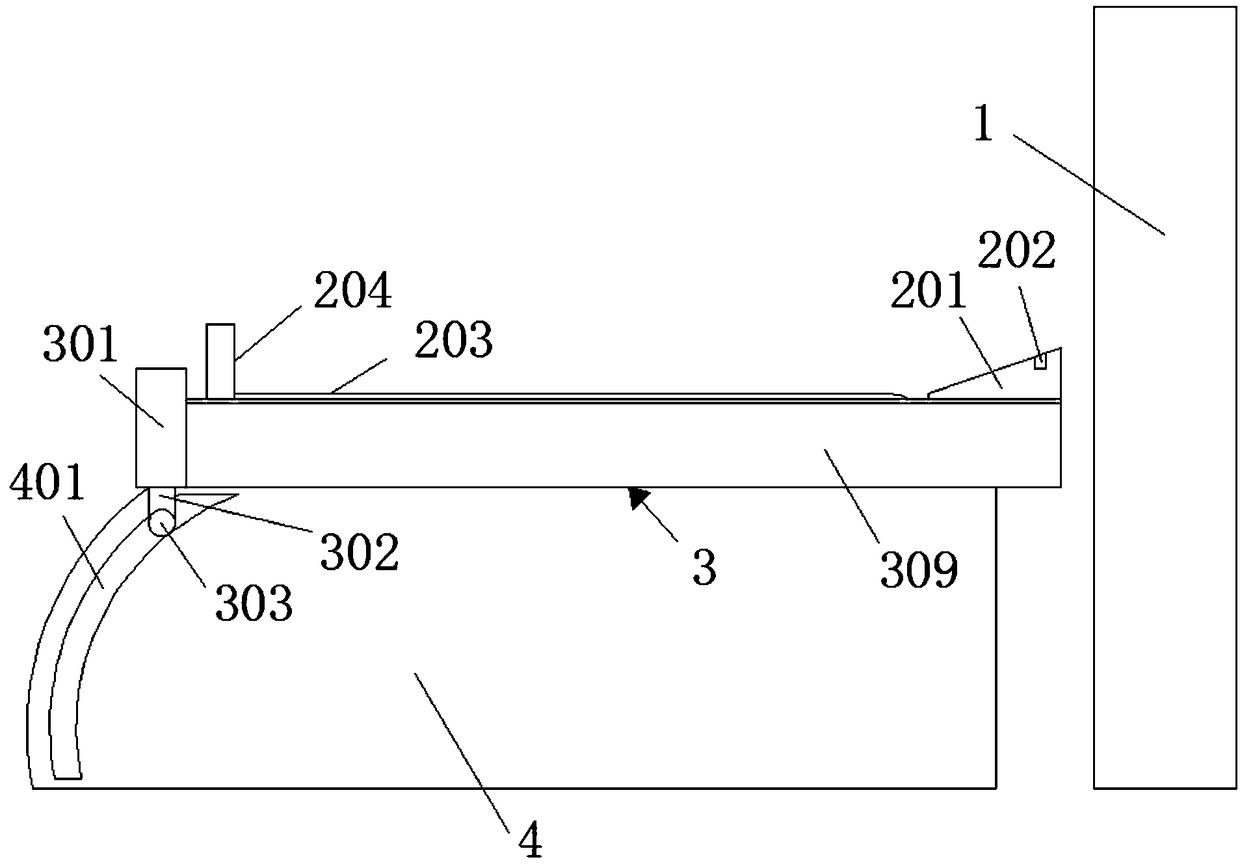
[0038] A medical CT scanning device, comprising a CT scanning frame 1 and an examination bed, the examination bed includes a bed board support part 3 and a sliding bed board 2 that can slide in the bed board support part 3, and one end of the sliding bed board 2 is provided with a headrest 201, The other end is provided with a moving device capable of pushing the inspection object lying on the sliding bed board to the headrest 201 .
Embodiment 2
[0040] This embodiment provides a kind of medical CT scanning equipment, such as Figure 1 to Figure 6 shown.
[0041] A medical CT scanning device, comprising a CT scanning frame 1 and an examination bed, the examination bed includes a bed board support part 3 and a sliding bed board 2 that can slide in the bed board support part 3, and one end of the sliding bed board 2 is provided with a headrest 201, The other end is provided with a moving device capable of pushing the inspection object lying on the sliding bed board to the headrest 201 .
[0042] The headrest 201 is provided with an infrared sensor 202 , and the infrared sensor 202 is perpendicular to the sliding bed board 2 ; the headrest 201 is arranged at the rear end of the sliding bed board 2 .
[0043] When the head of the inspection object moves above the infrared sensor 202 , the infrared sensor 202 can detect in real time to prevent the head of the inspection object from exceeding the headrest 201 .
Embodiment 3
[0045] This embodiment provides a kind of medical CT scanning equipment, such as Figure 1 to Figure 6 shown.
[0046] A medical CT scanning device, comprising a CT scanning frame 1 and an examination bed, the examination bed includes a bed board support part 3 and a sliding bed board 2 that can slide in the bed board support part 3, and one end of the sliding bed board 2 is provided with a headrest 201, The other end is provided with a moving device capable of pushing the inspection object lying on the sliding bed board to the headrest 201 .
[0047] The moving device includes a foot block 204 arranged on the top of the sliding bed board 2, the sliding bed board 2 is a hollow structure, the top of the sliding bed board 2 is provided with a chute A, two ends of the chute A are provided with two parallel guide rails A206, the guide rails A206 is parallel to the direction in which the sliding bed board 2 slides in the bed board support part 3; the bottom of the foot block 204 i...
PUM
 Abstract
Description
Claims
Application Information
 - Generate Ideas
- Intellectual Property
- Life Sciences
- Materials
- Tech Scout
- Unparalleled Data Quality
- Higher Quality Content
- 60% Fewer Hallucinations
Browse by: Latest US Patents, China's latest patents, Technical Efficacy Thesaurus, Application Domain, Technology Topic, Popular Technical Reports.
© 2025 PatSnap. All rights reserved.Legal|Privacy policy|Modern Slavery Act Transparency Statement|Sitemap|About US| Contact US: help@patsnap.com