Large space frame type gas collection lower flue structure

A frame-type, large-space technology, applied in the field of flue structure, can solve the problems of excessive fluoride discharge in the skylight of the electrolysis workshop, inability to protect the upper structure of the tank, and unbalanced gas collection effect of the flue system, etc. The effect of the upper smoke problem, the equal suction air collection efficiency, and the reduction of contact strength and deflection

Inactive Publication Date: 2019-01-04
SHENYANG ALUMINIUM MAGNESIUM INSTITUTE
View PDF6 Cites 2 Cited by
  • Summary
  • Abstract
  • Description
  • Claims
  • Application Information

AI Technical Summary

Problems solved by technology

[0002] The existing gas-collecting flue system of an aluminum electrolytic cell is divided into two structural forms, the upper flue and the lower flue. The traditional lower flue structure cannot maintain a uniform negative pressure in the tank chamber, which seriously unbalances the gas-collecting effect of the flue system. The phenomenon of smoke and material appearing on the part of the tank caused the discharge of fluoride in the skylight of the electrolysis workshop to exceed the standard; and a large amount of smoke was concentrated in the lower passage in the tank bore, which needed to bypass multiple shelling cylinders and feeding barrels, resulting in gas If the flow velocity is too large and the flow path is too long, powder accumulation is easy to form in the flue, which increases the resistance of the flue
The system resistance of the upper flue structure is small, and the gas collection effect is good, but the heat insulation protection of the upper structure of the tank cannot be carried out, resulting in a high temperature of the upper structure of the tank, and the parts such as cylinders, insulating pads, etc. are prone to aging, and due to the complex structure , making it difficult to install and overhaul the components on the upper part of the tank

Method used


Image

  • Large space frame type gas collection lower flue structure
  • Large space frame type gas collection lower flue structure
  • Large space frame type gas collection lower flue structure

Examples


Embodiment 1

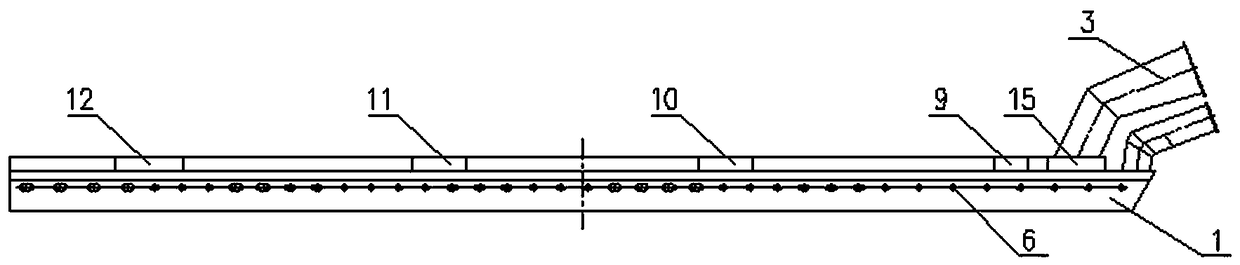
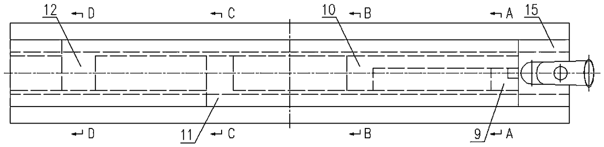
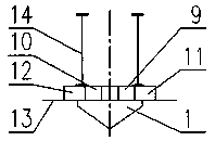
[0021] As shown in the figure, the large-space frame-type gas-gathering lower flue structure divides the gas-gathering lower flue 1 into 2-10 sections, and each section of the sub-flue is equipped with an independent branch pipe for separate gas collection, which converges in the collective smoke chamber 15, The summed smoke cavity 15 is connected with the main smoke exhaust pipe 3, the gas-collecting lower flue 1 is set at the bottom of the horizontal cover plate 13, each branch smoke pipe is welded above the horizontal cover plate 13, and the bottom of the girder 14 is welded to the bottom of the branch smoke pipe. top.

[0022] The gas-collecting lower flue 1 is divided into four sections, and the branch smoke pipes are the first smoke pipe 12, the second smoke pipe 11, the third smoke pipe 10 and the fourth smoke pipe 9, and each smoke pipe passes through The smoke pipe is connected to the collecting smoke chamber 15 .

[0023] Four cigarette pipes form a frame structure....

Embodiment 2

[0028] The gas-collecting lower flue 1 is divided into five sections, and the fifth section of the sub-flue opens at the bottom of the collection smoke chamber 15 . Others are with embodiment 1.


PUM


Abstract

The invention relates to a flue structure, in particular to a large space frame type gas collection lower flue structure. The large space frame type gas collection flue structure divides a gas collection lower flue into 2-10 segments, each segment of the flue is provided with separate branch smoke pipes for collecting gas separately, the gas is gathered into a main smoke chamber, the main smoke chamber is communicated with a main smoke exhaust pipe, the gas collection lower flue is arranged at the bottom of a horizontal cover plate, each branch smoke pipe is welded to the upper portion of thehorizontal cover plate, and the bottoms of girders are welded to the tops of the branch smoke pipes. According to the structure, a gas collection effect of the flue is improved, the contact area between the girders and the horizontal cover plate is increased, the strength of the girders is improved, the height of the girders can be effectively decreased, the height of an electrolysis plant is decreased at the same time, and the civil construction investment is saved.

Description

technical field [0001] The invention relates to a flue structure, in particular to a large-space frame type gas-collecting lower flue structure. Background technique [0002] The existing gas-collecting flue system of an aluminum electrolytic cell is divided into two structural forms, the upper flue and the lower flue. The traditional lower flue structure cannot maintain a uniform negative pressure in the tank chamber, which seriously unbalances the gas-collecting effect of the flue system. The phenomenon of smoke and material appearing on the part of the tank caused the discharge of fluoride in the skylight of the electrolysis workshop to exceed the standard; and a large amount of smoke was concentrated in the lower passage in the tank bore, which needed to bypass multiple shelling cylinders and feeding barrels, resulting in gas If the flow velocity is too large and the flow path is too long, powder accumulation is easy to form in the flue, which increases the resistance of...

Claims


Application Information

Patent Timeline
Patent Type & Authority Applications(China)
IPC IPC(8): C25C3/22
CPCC25C3/22
Inventor 王富强周东方刘雅锋
Owner SHENYANG ALUMINIUM MAGNESIUM INSTITUTE
Why Eureka
Try Eureka