Gallery underground cavity high side wall construction equipment and construction method

A technology for underground caverns and construction equipment, which can be applied to artificial islands, water conservancy projects, underwater structures, etc., and can solve problems such as increased construction risks for high-altitude operations, large engineering volume, and prone to misplaced platforms

Inactive Publication Date: 2019-01-04
SINOHYDRO BUREAU 8 CO LTD
View PDF4 Cites 1 Cited by
  • Summary
  • Abstract
  • Description
  • Claims
  • Application Information

AI Technical Summary

Problems solved by technology

[0002] At present, due to reasons such as the removal or replacement of supports in the construction of high side walls in corridor-type underground caverns, the side wall structure is generally spliced ​​with small steel formwork. The following problems existed in the construction process: First, due to the high height of the high side walls of the corridor-type underground cavern, scaffolding needs to be erected and dismantled continuously, the amount of work is large, the labor intensity of the workers is high, and the turnover of scaffolding is slow, which greatly reduces the utilization rate. The second is that small formwork is used for splicing, resulting in many construction joints, which are prone to misplacement, which affects the construction quality of the side wall, and the construction period is longer; third, manual erection of scaffolding and vertical formwork are all high-altitude operations, which greatly increases Construction risks of working at heights

Method used


Image

  • Gallery underground cavity high side wall construction equipment and construction method
  • Gallery underground cavity high side wall construction equipment and construction method
  • Gallery underground cavity high side wall construction equipment and construction method

Examples


Embodiment Construction

[0033] The present invention will be further described in detail below with reference to the drawings and specific embodiments of the specification.

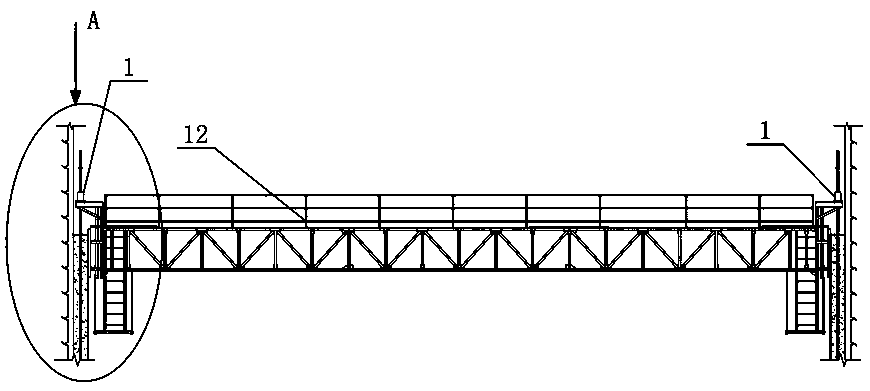
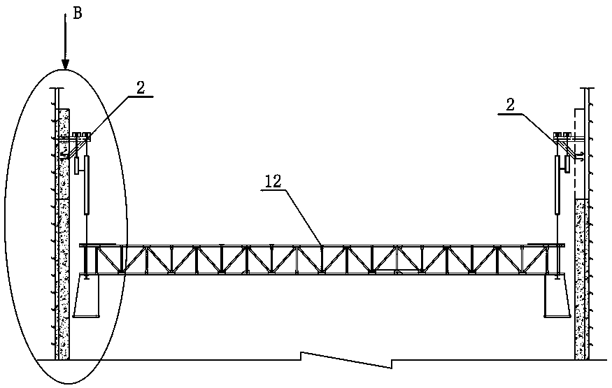
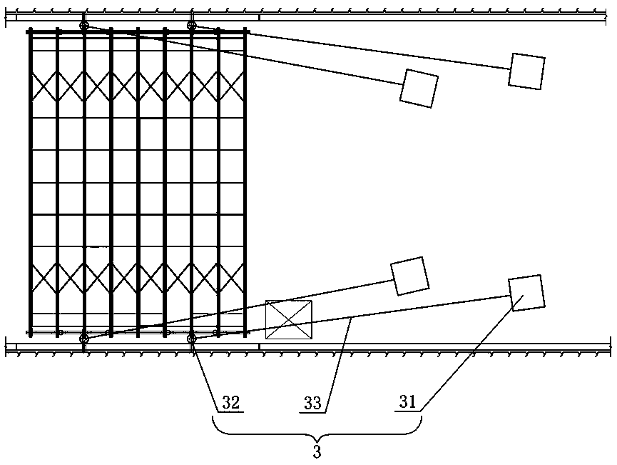
[0034] Figure 1 to Figure 7 The construction equipment for the high side wall of the long corridor underground cavern of this embodiment is shown, including a lifting slip form construction device 1, a wall top tensioning device 2 and a lowering device 3. The lifting slip form construction device 1 includes a truss construction platform 12. The truss construction platform 12 is set up between the side walls on both sides of the cavern. Both sides of the truss construction platform 12 are provided with slipforms 13, and vertical guide rods 11 are arranged between the slipforms 13 and the adjacent side walls. The straight guide rod 11 is equipped with a climbing rod hydraulic jack 14, and the truss construction platform 12 is fixed on each climbing rod hydraulic jack 14. When the top of the side wall is constructed, the wall top tens...


PUM


Abstract

The invention discloses gallery underground cavity high side wall construction equipment. The equipment comprises a lifting slide mold construction device, a wall top pull fixing device and a placingdevice; the lifting slide mold construction device comprises a truss construction platform; the truss construction platform is built between two side walls of a cavity; slide molds are arranged on twobackup wall sides of the truss construction platform; vertical guide rods are arranged between the slide molds and near side walls; climbing rod type hydraulic jacks sleeve the vertical guide rods; the truss construction platform is fixedly mounted on each climbing rod type hydraulic jack; when the tops of the side walls are constructed, the hung truss construction platform is tensioned by the wall top pull fixing device; and after the tops of the side walls are constructed, the truss construction platform is put down by the placing device. A construction method comprises the steps of building of the lifting slide mold construction device, casting of side wall concrete, mounting of the wall top pull fixing device, placement of the truss construction platform and shifting of the truss construction platform to adjacent construction places; and the steps are repeated. The construction equipment and the construction method have the advantages of safe operation, high construction efficiency and good construction quality.

Description

Technical field [0001] The invention belongs to the construction technology of the side wall of a cavern, and in particular relates to a long corridor type underground cavern high side wall construction equipment and a construction method. Background technique [0002] At present, due to support removal or support replacement in the construction of the high side wall of the long corridor underground cavern, the side wall structure generally adopts small steel formwork for splicing. The supporting system is steel pipe scaffolding plus square timber or I-steel back ribs. The following problems existed in the construction process: First, due to the high height of the high side walls of the corridor-type underground caverns, the scaffolding needs to be continuously erected and removed. The amount of work is large, the labor intensity of the workers is high, and the scaffolding turnover is slow, which greatly reduces the utilization. Second, the use of small formwork splicing results ...

Claims


Application Information

Patent Timeline
IPC IPC(8): E02D29/045E04G11/28
CPCE02D29/045E04G11/28
Inventor 侯伏强邓常义刘豫郭大军陈清
Owner SINOHYDRO BUREAU 8 CO LTD
Why Eureka
Try Eureka