
Overspeed protection and flow control device for pumped storage power station

A technology of pumped storage power station and flow control device, which is applied in the directions of hydroelectric power generation, safety devices, engine components, etc., can solve the problems of long valve group response time, low mechanical adjustment accuracy, complicated system pipeline layout, etc., to achieve convenient The effect of observing and troubleshooting, high versatility and interchangeability, and simple electrical control logic

Pending Publication Date: 2019-01-04
DONGFANG ELECTRIC AUTOMATIC CONTROL ENG CO LTD +1
View PDF22 Cites 3 Cited by
  • Summary
  • Abstract
  • Description
  • Claims
  • Application Information

AI Technical Summary

Problems solved by technology

[0013] 1. It cannot meet the requirements of multi-rate start-up and shutdown, emergency shutdown and over-speed protection comprehensive control of pumped storage units. To varying degrees, the layout of each functional valve group is too scattered, the mechanical adjustment accuracy is not high and the adjustment is very inconvenient, and it takes a long time After running, it will cause the set point to drift, which will affect the reliability of power plant operation.
[0014] 2. The pipeline layout of the system is complicated, and too long connecting pipelines will easily cause many oil leakage points, too long valve group response time, and untimely switching of system status; too many connecting nozzles and control oil pipe joints will affect the installation position. High requirements, if the installation position is unreasonable, it is easy to cause pressure fluctuations between the nozzles, resulting in misoperation of hydraulic control functions, which seriously affects the operation safety of the power station

Method used


Image

  • Overspeed protection and flow control device for pumped storage power station
  • Overspeed protection and flow control device for pumped storage power station

Examples


Embodiment 1

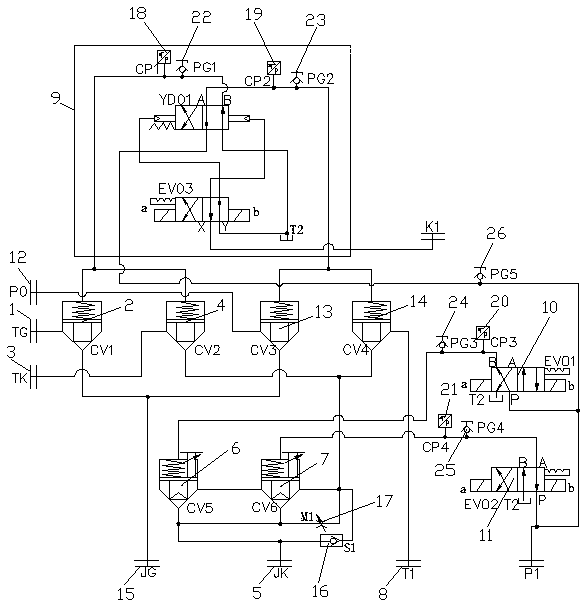
[0041] An overspeed protection and flow control device for a pumped storage power station, comprising a control pressure oil circuit, a first cartridge valve 2 connected to the closing chamber 1 of the main pressure distribution valve through the main oil circuit, and a first cartridge valve 2 connected to the main pressure distribution valve through the main oil circuit. The second cartridge valve 4 on the valve opening chamber 3, the first section closing cartridge valve 6 and the second section closing cartridge valve 7 connected to the servomotor opening chamber 5, also includes the oil return tank 8, the pilot type Electro-hydraulic reversing valve 9, first segment closing pilot solenoid valve 10 for switching first segment closing cartridge valve 6, second segment closing pilot solenoid valve for switching second segment closing cartridge valve 7 Valve 11, the first emergency cartridge valve 13 connected to the main pressure oil source 12 and the second emergency cartridg...

Embodiment 2

[0044] An overspeed protection and flow control device for a pumped storage power station, comprising a control pressure oil circuit, a first cartridge valve 2 connected to the closing chamber 1 of the main pressure distribution valve through the main oil circuit, and a first cartridge valve 2 connected to the main pressure distribution valve through the main oil circuit. The second cartridge valve 4 on the valve opening chamber 3, the first section closing cartridge valve 6 and the second section closing cartridge valve 7 connected to the servomotor opening chamber 5, also includes the oil return tank 8, the pilot type Electro-hydraulic reversing valve 9, first segment closing pilot solenoid valve 10 for switching first segment closing cartridge valve 6, second segment closing pilot solenoid valve for switching second segment closing cartridge valve 7 Valve 11, the first emergency cartridge valve 13 connected to the main pressure oil source 12 and the second emergency cartridg...

Embodiment 3

[0049] An overspeed protection and flow control device for a pumped storage power station, comprising a control pressure oil circuit, a first cartridge valve 2 connected to the closing chamber 1 of the main pressure distribution valve through the main oil circuit, and a first cartridge valve 2 connected to the main pressure distribution valve through the main oil circuit. The second cartridge valve 4 on the valve opening chamber 3, the first section closing cartridge valve 6 and the second section closing cartridge valve 7 connected to the servomotor opening chamber 5, also includes the oil return tank 8, the pilot type Electro-hydraulic reversing valve 9, first segment closing pilot solenoid valve 10 for switching first segment closing cartridge valve 6, second segment closing pilot solenoid valve for switching second segment closing cartridge valve 7 Valve 11, the first emergency cartridge valve 13 connected to the main pressure oil source 12 and the second emergency cartridg...


PUM


Abstract

The invention discloses an overspeed protection and flow control device for a pumped storage power station, and belongs to the technical field of pumped storage. The overspeed protection and flow control device for the pumped storage power station comprises a first cartridge inserted valve, a second cartridge inserted valve, a first segmentation closing cartridge inserted valve and a second segmentation closing cartridge inserted valve. The overspeed protection and flow control device for the pumped storage power station is characterized in that the overspeed protection and flow control devicefor the pumped storage power station further comprises an oil return tank, a pilot-operated type electro-hydraulic reversing valve, a first segmentation closing pilot-operated electromagnetic valve,a second segmentation closing pilot-operated electromagnetic valve, a first accident cartridge inserted valve and a second accident cartridge inserted valve, the first accident cartridge inserted valve and the second accident cartridge inserted valve are correspondingly connected to a servomotor closing cavity, the second accident cartridge inserted valve is connected with the oil return tank, andthe pilot-operated type electro-hydraulic reversing valve is correspondingly connected with control cavities of the first accident cartridge inserted valve, the second accident cartridge inserted valve, the first cartridge inserted valve and the second cartridge inserted valve. The accident cartridge inserted valves, the segmentation closing cartridge inserted valves and the second segmentation closing pilot-operated electromagnetic valves are highly integrated into a whole, the connection of oil pipelines is reduced, the disadvantage of many leakage points is avoided, and the reliability andsafety of unit operation are improved.

Description

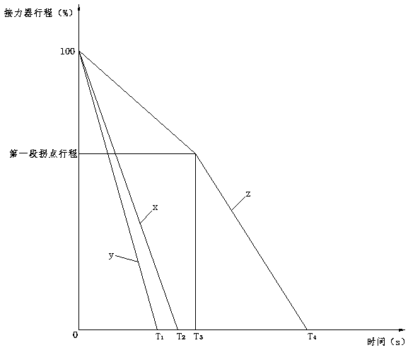
technical field [0001] The invention relates to the technical field of pumped storage energy, in particular to an overspeed protection and flow control device for a pumped storage power station. Background technique [0002] The overspeed protection and flow control device is the key protection equipment of the speed regulation system of the hydropower station. Its main functions are: unit accident shutdown, overspeed shutdown and servomotor multi-stage speed shutdown. In the event of an emergency of the unit, the governor cannot be shut down normally, and the guide vane servomotor cannot be closed in time, the speed of the unit will quickly rise to the runaway speed. In order to limit the overspeed of the unit and avoid the occurrence of runaway accidents, accident protection Or the mechanical overspeed protection device in this case shall close the guide vane servomotor in time according to the closing rate calculated by the unit adjustment and maintenance, so as to protec...

Claims


Application Information

Patent Timeline
Patent Type & Authority Applications(China)
IPC IPC(8): F03B15/06F03B15/18F03B13/06
CPCF03B13/06F03B15/06F03B15/18Y02E10/20Y02E60/16
Inventor 贾小平王志力王丽萍
Owner DONGFANG ELECTRIC AUTOMATIC CONTROL ENG CO LTD
Learn More