Centrifugal water pump formed through spinning-stamping welding of steel plates

A technology of stamping welding and centrifugal water pumps, which is applied in the field of stamping welding centrifugal water pumps and steel plate spinning. It can solve the problems that it is difficult to overcome the radian of the blades on the impeller, the rough environment of the product, and a large amount of labor. It can get rid of casting trachoma, good sealing, and The effect of improving efficiency

Inactive Publication Date: 2019-01-04
李宏运
View PDF15 Cites 0 Cited by
  • Summary
  • Abstract
  • Description
  • Claims
  • Application Information

AI Technical Summary

Problems solved by technology

[0003] The existing technology is foundry foundry pouring technology, this kind of technology needs a lot of space and a lot of labor when foundry
Molten iron is needed during pouring, which will generate a lot of pollution. At the same time, the products produced not only have a high scrap rate but also semi-finished products, which require secondary processing.
[0004] The current pump casing, bearing body casing, water inlet, water outlet, tee, and kill head are all cast and sand casting processes. The products produced are not only rough, but the casting process will also cause great pollution to the environment.
[0005] The impeller is the core of the centrifugal water pump. At present, the casting casting process is also used. This process is difficult to overcome the arc required by the blades on the impeller. The centrifugal force of the impeller rotation can only be used to pump water.

Method used


Image

  • Centrifugal water pump formed through spinning-stamping welding of steel plates
  • Centrifugal water pump formed through spinning-stamping welding of steel plates
  • Centrifugal water pump formed through spinning-stamping welding of steel plates

Examples


Embodiment

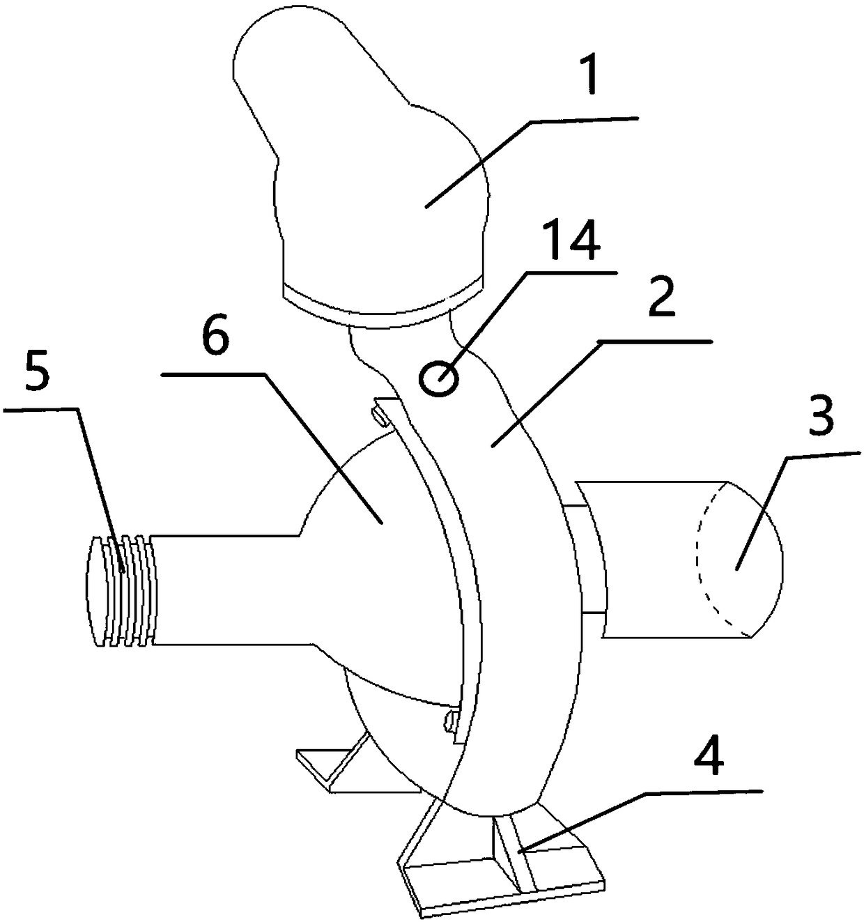
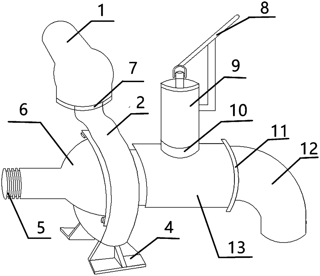
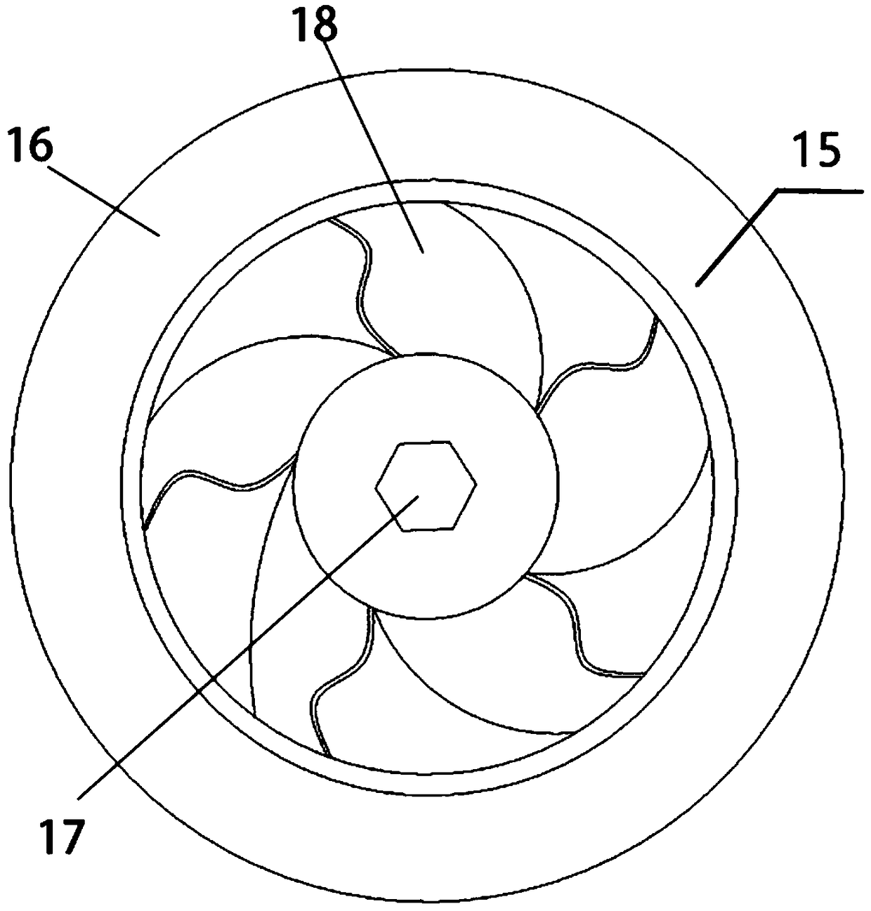
[0033] Such as Figure 1-4 , a steel plate spinning, stamping and welding centrifugal water pump, including two assembly methods: one of them is: steel plate spinning, stamping and welding simple centrifugal water pump, which is composed of a steel plate elbow water outlet 1, a steel plate shell 2, and a steel plate directly Water inlet 3, steel plate pump leg 4, belt pulley 5, steel plate bearing body shell 6, air release valve 14, and steel plate closed impeller 15; It consists of steel plate elbow water outlet 1, steel plate shell 2, steel plate elbow water inlet 12, steel plate pump leg 4, pulley 5, steel plate bearing body shell 6, water outlet check valve 7, water inlet check valve 11, pressure Well head check valve 10, well kill head cylinder body 9, well kill head pressure handle 8, steel plate tee 13, steel plate closed impeller 15, side cover 16, transmission shaft 17, and blade 18 is formed.

[0034]Steel plate spinning, stamping and welding The steel plate closed ...


PUM


Abstract

The invention discloses a centrifugal water pump formed through spinning-stamping welding of steel plates. According to one assembling method, the steel plates are welded after being spun and stamped,so that the simple centrifugal water pump is formed. According to the other assembling method, the steel plates are welded after being spun and stamped, so that the centrifugal water pump provided with a well killing head is formed. By adoption of the centrifugal water pump based on the novel process, the defects of the prior art are overcome. The centrifugal water pump is formed by the steel plates which are spun and stamped and are then welded, so that all parts of the whole water pump do not need to be machined through a traditional casting process which can cause severe pollution; all thesteel plates forming the centrifugal water pump are welded after being spun and stamped, so that all the parts of the water pump are more durable and lighter; and the production speed is high, the quality is high, and the time, cost, strength and labor are saved at the same time.

Description

technical field [0001] The invention relates to a steel plate spinning, stamping and welding centrifugal water pump. Background technique [0002] At present, there are two types of centrifugal water pumps on the market. One is simple: it consists of a water inlet tap (including a check valve), a water delivery pipe, and a pump head. A centrifugal water pump. The other is to add a tee on the water inlet on a simple basis, and a centrifugal water pump with a kill head on the tee. [0003] Existing techniques are all foundry foundry pouring techniques, which require a large space and a large amount of labor when foundry. Melt iron needs to be melted during pouring, which will generate a lot of pollution. At the same time, the products produced not only have a high scrap rate but also semi-finished products, which require secondary processing. [0004] The current pump casing, bearing body casing, water inlet, water outlet, tee, and kill head are all cast and foundry casting...

Claims


Application Information

Patent Timeline
Patent Type & Authority Applications(China)
IPC IPC(8): F04D1/00F04D13/02F04D29/02F04D29/42F04D29/22
CPCF04D1/00F04D13/02F04D29/026F04D29/2227F04D29/4266F04D29/4293
Inventor 李宏运
Owner 李宏运
Why Eureka
Try Eureka