Electric fan head swing angle adjusting device

A technology for regulating devices and electric fans, applied in pump devices, pump control, non-variable pumps, etc., can solve problems such as difficult to use, irregular disorder, high production costs, etc., to improve stability and effectiveness, and prolong work The effect of service life and reduction of production cost

Active Publication Date: 2019-01-04
蒋亮健
View PDF12 Cites 6 Cited by
  • Summary
  • Abstract
  • Description
  • Claims
  • Application Information

AI Technical Summary

Problems solved by technology

However, since the joint type between the conductive contact of the slider and the conductive signal conversion substrate is a frictional sliding elastic pressure contact changing device, as the use time prolongs, the more reciprocating sliding friction of the slider, the greater the friction between the conductive contact and the substrate. There will be more serious wear and oxidation (electrocorrosion). Due to the uneven thickness of the oxide layer and the uneven elastic pressure contact of the conductive contact, the sampling electrical signal fed back and transmitted during the angle adjustment operation often appears irregular and disordered. , leading to the failure of the operation of the angle adjustment control chip, which makes the adjustment and control of the electric fan swing angle fail, which needs to be improved
In addition, due to the small space of the variable-angle gearbox housing, the reciprocating mechanical action process of the built-in cam-follower-swing rod mechanical sampling mechanism is relatively short, generally only a few millimeters in stroke, and there are many reciprocating mechanisms. , the cumulative work difference of various coordination is large, resulting in the reciprocating mechanical sampling mechanism superimposed on the conductive contact of the slider - the sampling electrical signal output by the conductive signal conversion substrate transmission device has a low resolution, and the production cost is high, so it is difficult to meet the angle adjustment requirements. It is used in electric fans with slightly higher precision, which also needs to be improved

Method used


Image

  • Electric fan head swing angle adjusting device
  • Electric fan head swing angle adjusting device
  • Electric fan head swing angle adjusting device

Examples


Embodiment Construction

[0022] The present invention will be further described below with embodiment and accompanying drawing:

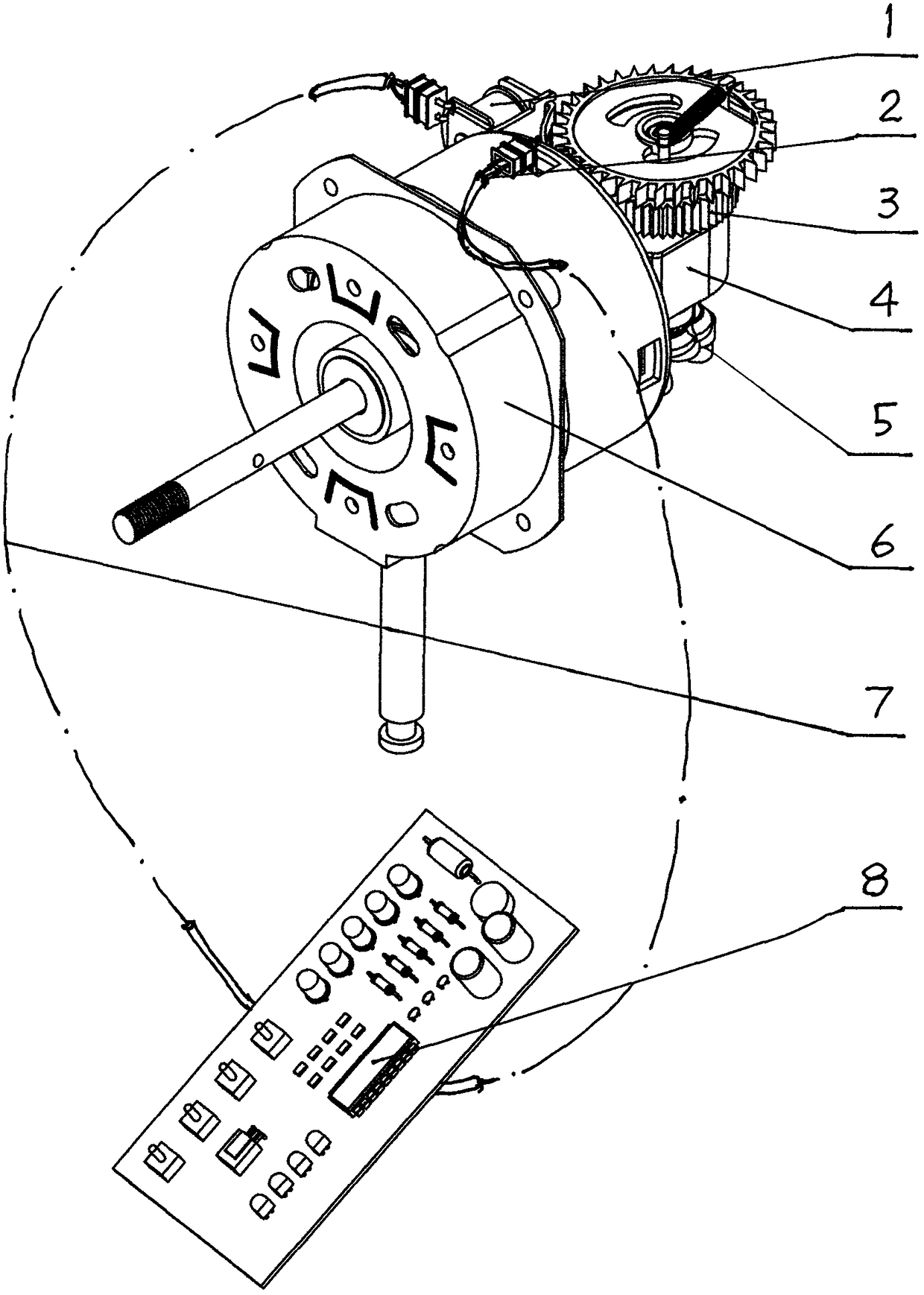
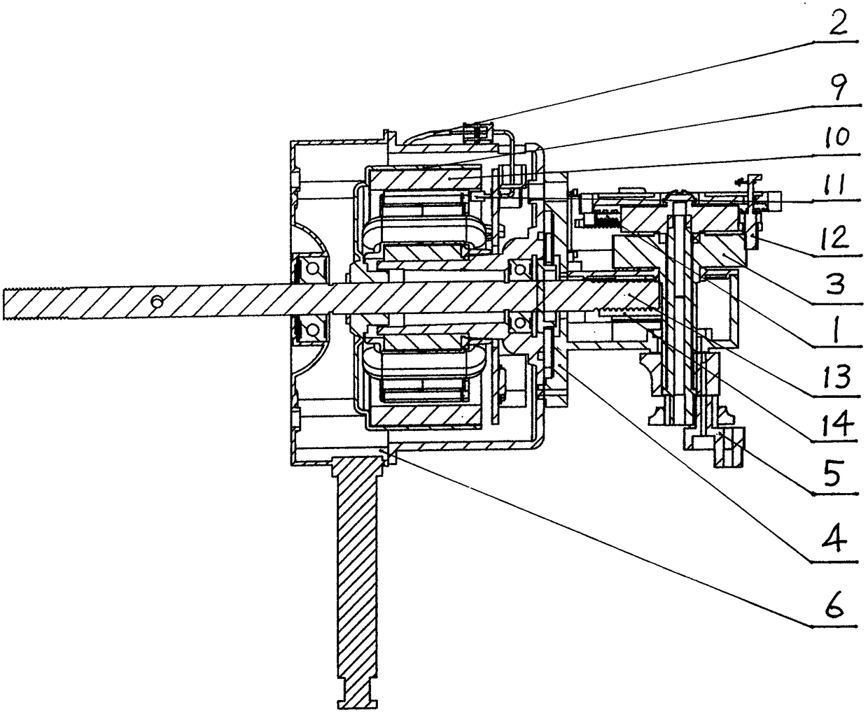
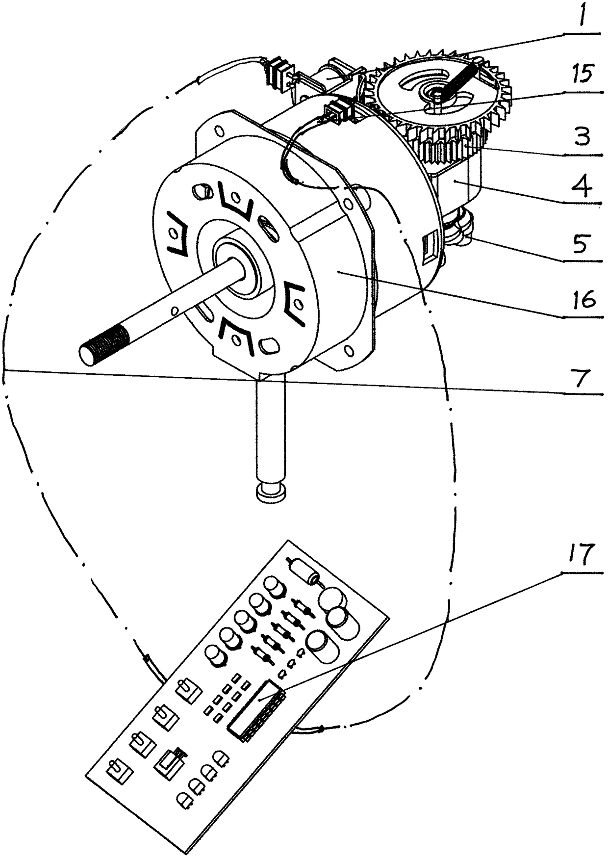
[0023] refer to figure 1 and figure 2 , the present invention comprises outer rotor permanent magnet brushless DC motor 6, a cover is made up of worm screw 13—worm gear 14—worm gear shaft—big gear 3 power transmission mechanism, planetary gear crank 5 mechanism and big gear 3—pawl 12 A variable-angle gearbox 4 composed of a clutch device. The housing of the variable-angle gearbox 4 is equipped with a magnetic attraction device 1. The magnetic attraction device 1 is connected to the angle adjustment control chip 8 through a wire 7. The rotor of the permanent magnet brushless DC motor 6 on the outer rotor 9 is equipped with a permanent magnet 10 magnetic poles, and the permanent magnet 10 magnetic poles become the rotor 9 markers that rotate together with the rotor, and a Hall sensor 11 is placed in the corresponding gap of the permanent magnet 10, and the Hall sensor 11 is...


PUM


Abstract

The invention discloses an electric fan head swing angle adjusting device and an angle adjusting sampling electric signal data acquisition method. A rotor marker is arranged on a motor, a rotor position sensing signal acquisition device is arranged at the position, corresponding to the rotor marker, of the rotor marker, and the rotor position sensing signal acquiring device is connected with an angle adjusting control chip through a wire; in order to enable an angle-adjusting sampling electric signal data acquired by the motor rotor position sensing signal acquisition device to correspond to an angle-adjusting process planetary gear crank-variable-length action track and have a rule, the positions of a reference zero point and a maximum displacement inflection point of the planetary gear crank are required to be defined, and according to the established transmission ratio and logical conversion of a power transmission mechanism of a variable-angle gearbox, the motor rotor operates in the angle adjusting process, a regular sampling electric signal data corresponding to the variable-length action track of the planetary gear crank can be obtained, and the device has the characteristics of being free of contact type sampling, stable, reliable and low in cost.

Description

technical field [0001] The invention relates to an electric fan oscillating device, in particular to an electric fan oscillating angle adjustment device. The invention also relates to a sampling electric signal acquisition method of the swing angle adjusting device. Background technique [0002] An existing electric fan swing angle adjustment device (China Special Issue No. 200510037286.1) is characterized in that it consists of a set of worm-worm gear-worm shaft-big gear power transmission mechanism, planetary crank mechanism and large gear ——In the variable-angle gear box composed of the pawl clutch device, a set of reciprocating mechanical sampling device composed of cam-follower-swing rod is set, and the fork at the end of the reciprocating mechanical sampling device A set of sampling electrical signal conversion device is installed on the conductive signal conversion substrate with the slider conductive contact for reciprocating sliding. The sampling electrical signal ...

Claims


Application Information

Patent Timeline
Patent Type & Authority Applications(China)
IPC IPC(8): F04D25/10F04D27/00
CPCF04D25/105F04D27/00
Inventor 蒋亮健
Owner 蒋亮健
Why Eureka
Try Eureka