Rail visual inspection two-dimensional and three-dimensional fusion imaging system
A three-dimensional imaging and two-dimensional imaging technology, which is applied in measuring devices, material analysis through optical means, instruments, etc., can solve problems such as difficult to effectively determine loose bolts and foreign objects in the ballast bed, and achieve the effect of reducing the overall size
- Summary
- Abstract
- Description
- Claims
- Application Information
AI Technical Summary
Problems solved by technology
Method used
Image
Examples
Embodiment 1
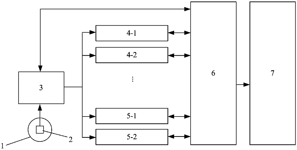
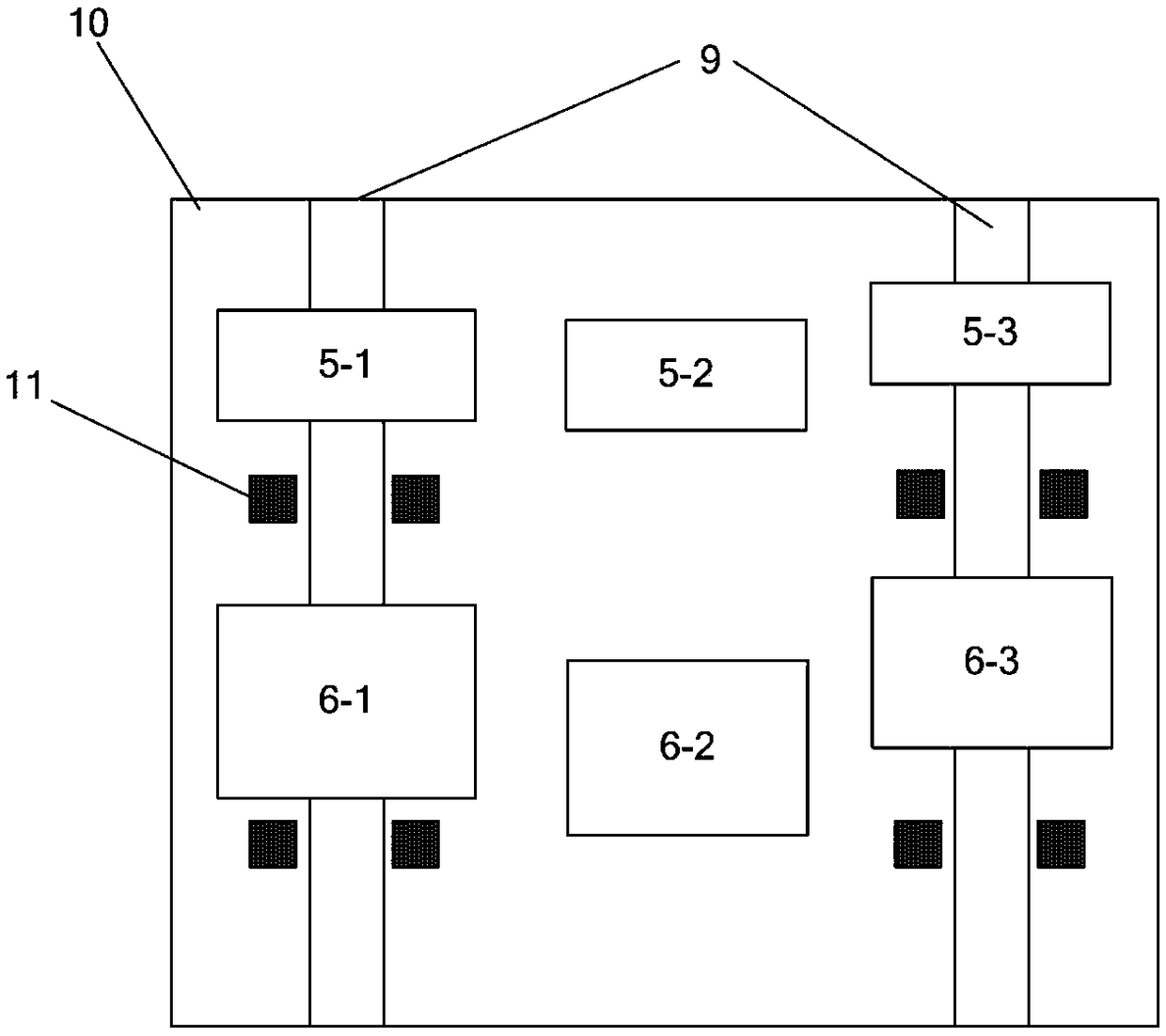
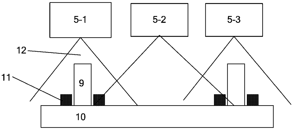
[0033] like figure 1 As shown in the figure, a two-dimensional and three-dimensional fusion imaging system for track visual inspection is composed of a two-dimensional and three-dimensional imaging module, an imaging control module, a data acquisition module 7, and a two-dimensional and three-dimensional data fusion module 8, wherein the two-dimensional and three-dimensional imaging The module is composed of n1 two-dimensional imaging devices 4 and n2 three-dimensional imaging devices 5, where n1=3 and n2=3. n1 sets of 2D imaging devices perform 2D imaging on the fastener system, rail system and ballast system of the track through field of view splicing, and obtain the texture image of the full section of the track. The three-dimensional imaging of the rail system, the rail system, and the track bed system is performed to obtain the three-dimensional topography data of the full section of the track. The positions of n1 two-dimensional imaging devices and n2 three-dimensional i...
Embodiment 2
[0041] The difference from Embodiment 1 is that the illumination light source in the two-dimensional imaging device 4 is a strip light source formed by k2 LED lamp beads collinear and serially arranged; the illumination light source illuminates the track surface obliquely downward, The area completely covers the imaging area of the line array camera; the angle between the illumination direction of the light source and the imaging direction of the line array camera is a, a=60 degrees, and k2=10. The strip light source and the line scan camera constitute dark-field illumination imaging, which can weaken the strong reflected light on the top of the rail in Example 1, and explicitly image the defects on the top of the rail.
Embodiment 3
[0043] The difference from Embodiment 2 is that the illumination light source in the two-dimensional imaging device 4 and the central line structured light of the three-dimensional imaging device are both near-infrared light sources, and a narrow-band filter with a corresponding wavelength is set at the front end of the line array camera and the front end of the 3D camera to eliminate the Ambient light interference.
PUM
| Property | Measurement | Unit |
|---|---|---|
| Wavelength | aaaaa | aaaaa |
Abstract
Description
Claims
Application Information
 - R&D
- Intellectual Property
- Life Sciences
- Materials
- Tech Scout
- Unparalleled Data Quality
- Higher Quality Content
- 60% Fewer Hallucinations
Browse by: Latest US Patents, China's latest patents, Technical Efficacy Thesaurus, Application Domain, Technology Topic, Popular Technical Reports.
© 2025 PatSnap. All rights reserved.Legal|Privacy policy|Modern Slavery Act Transparency Statement|Sitemap|About US| Contact US: help@patsnap.com


