
Bistatic Spotlight SAR Large Scene Imaging Method Applicable to Complex Flight Trajectories

A technology of flight trajectory and imaging method, which is applied in the direction of using re-radiation, radio wave reflection/re-radiation, instruments, etc., can solve the problems of inability to meet high-precision imaging, limit the size of imaging scenes, and uniform focus of large scenes, and achieve the goal of overcoming Poor adaptability to complex trajectories, improved effective focus depth of field, and high imaging processing effects

Active Publication Date: 2020-09-08
UNIV OF ELECTRONICS SCI & TECH OF CHINA
View PDF4 Cites 0 Cited by
  • Summary
  • Abstract
  • Description
  • Claims
  • Application Information

AI Technical Summary

Problems solved by technology

Literature "Wu, J., Li, Z., Huang, Y., Yang, J., & Liu, Q.H.A generalized omega-k algorithm to process translationally variant bistatic-sar data based on two-dimensional stolt mapping. IEEE Transactions on Geoscience & RemoteSensing, 52 (10), 6597-6614, 2014 "approximately modeled the spatial variation of the echo signal spectrum parameters as linear, which improved the effective scene range of uniform focus to a certain extent, but when the scene size further increased, the linear approximation still failed. Meet the requirements of high-precision imaging
On the other hand, the theoretical research on SAR imaging methods often models the flight of the radar platform as a uniform linear motion, but in actual work, the platform flight often has certain maneuvers, and the high-order components of the motion trajectory will bring significant phase errors. Further limit the effective imaging scene size
In the current research results on the bistatic spotlight SAR imaging method, there is no method that can simultaneously solve the two problems of complex flight trajectories and large scene consistent focusing on the premise of ensuring the efficiency of the algorithm.

Method used


Image

  • Bistatic Spotlight SAR Large Scene Imaging Method Applicable to Complex Flight Trajectories
  • Bistatic Spotlight SAR Large Scene Imaging Method Applicable to Complex Flight Trajectories
  • Bistatic Spotlight SAR Large Scene Imaging Method Applicable to Complex Flight Trajectories

Examples


Embodiment Construction

[0039] In order to make the object, technical solution and advantages of the present invention clearer, the present invention will be further described in detail below in conjunction with the accompanying drawings and embodiments. It should be understood that the specific embodiments described here are only used to explain the present invention, not to limit the present invention.

[0040] In order to describe content of the present invention conveniently, at first the following terms are explained:

[0041] Term 1: Bistatic Synthetic Aperture Radar (BiSAR)

[0042] Bistatic synthetic aperture radar means that during the movement of the radar platform, the antenna of the transmitting station illuminates the imaging area, and the antenna of the receiving station receives the scattered echoes of the target in the imaging area; The processing algorithm compensates the Doppler phase of the azimuth signal to realize the azimuth aperture synthesis to form high-resolution azimuth, t...


PUM


Abstract

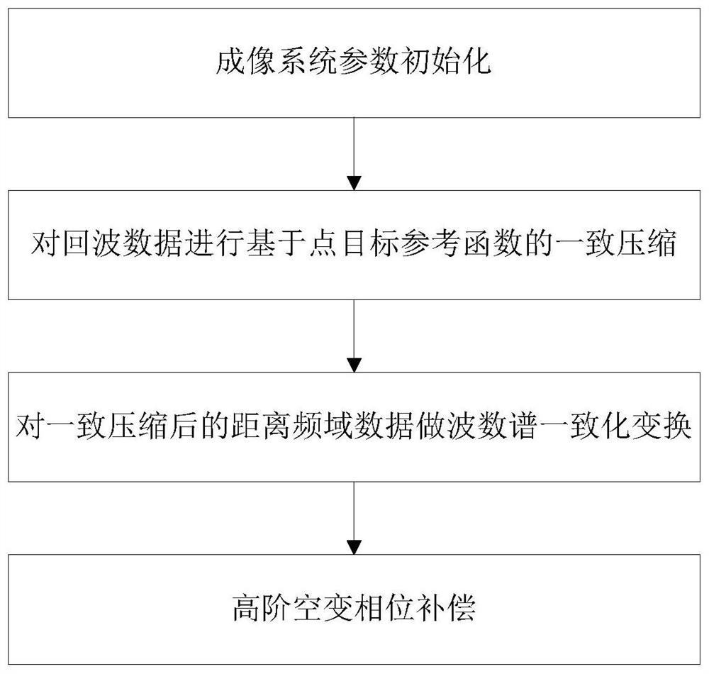
The invention discloses a bistatic spotlight SAR large-scene imaging method suitable for complex flight trajectories, which includes initializing imaging system parameters, performing consistent compression on echo data based on a point target reference function, and performing consistent compression on the uniformly compressed range-frequency The wavenumber spectrum consistent transformation is performed on the domain data, and the high-order space-varying phase compensation imaging is performed. The invention adopts the wave number spectrum unification method based on the assumption of linear space variation to realize the uniform focusing of SAR echoes under complex flight trajectories, and improves the effective focus depth of field through high-order space-variation phase compensation, and realizes the large-scale dual-base SAR under complex flight trajectories. Scene imaging processing can realize high-resolution imaging processing in a large imaging scene range, so that aircraft equipped with bistatic SAR systems can perform better in fields such as battlefield reconnaissance and surveillance, material airdrops, and earthquake disaster rescue.

Description

technical field [0001] The invention belongs to the technical field of radar signal processing, and in particular relates to a bistatic spotlight SAR large-scene imaging method suitable for complex flight trajectories. Background technique [0002] As an active aviation and aerospace remote sensing method, microwave imaging technology has the characteristics of all-day and all-weather work, and has been widely used in geological surveying and mapping, disaster monitoring, military reconnaissance and other fields. One of the most important means of global resource management. However, due to the limitations of its own working system, the existing Synthetic Aperture Radar (SAR, Synthetic Aperture Radar) cannot achieve high-resolution imaging in the azimuth direction of the forward-looking area, so that SAR can be used in aircraft forward-looking to the ground, autonomous landing, material airdrops, missiles, etc. Terminal guidance and other aspects can not fully play a role. ...

Claims


Application Information

Patent Timeline
Patent Type & Authority Patents(China)
IPC IPC(8): G01S13/90
CPCG01S13/90G01S13/9052G01S13/9058
Inventor 武俊杰缪昱宣王雯璟陈天夫李易李中余杨建宇
Owner UNIV OF ELECTRONICS SCI & TECH OF CHINA
Learn More