PFA wavefront bending correction method for bistatic bunching SAR suitable for any platform track

A bending correction, platform technology, applied in the direction of using re-radiation, radio wave measurement system, radio wave reflection/re-radiation, etc., to achieve high resolution, resolution, and high imaging processing effects

Active Publication Date: 2019-01-04
UNIV OF ELECTRONIC SCI & TECH OF CHINA
View PDF6 Cites 12 Cited by
  • Summary
  • Abstract
  • Description
  • Claims
  • Application Information

AI Technical Summary

Problems solved by technology

[0004] The purpose of the present invention is: in order to solve the application defects of the existing PFA wavefront bending correction method in the actual

Method used

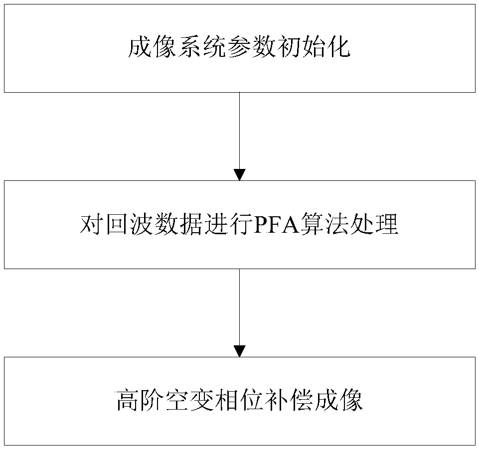
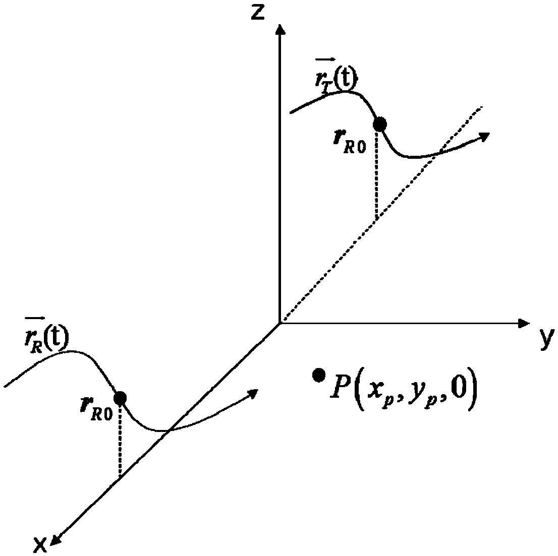
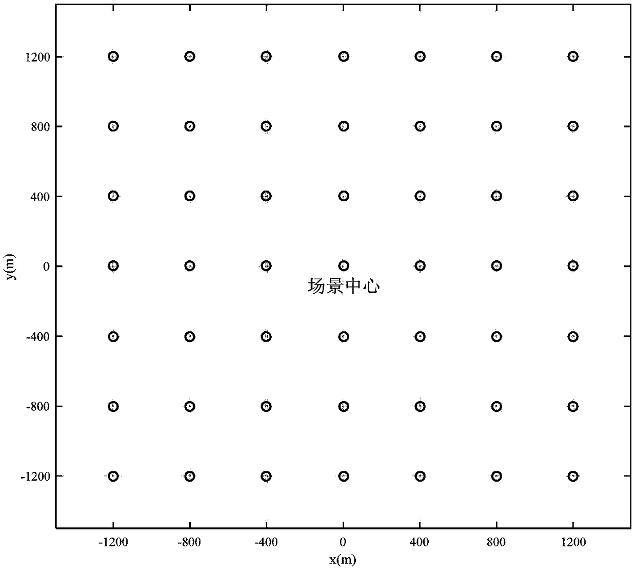

Image

  • PFA wavefront bending correction method for bistatic bunching SAR suitable for any platform track
  • PFA wavefront bending correction method for bistatic bunching SAR suitable for any platform track
  • PFA wavefront bending correction method for bistatic bunching SAR suitable for any platform track

Examples


Embodiment Construction

[0032] In order to make the object, technical solution and advantages of the present invention clearer, the present invention will be further described in detail below in conjunction with the accompanying drawings and embodiments. It should be understood that the specific embodiments described here are only used to explain the present invention, not to limit the present invention.

[0033] In order to describe content of the present invention conveniently, at first the following terms are explained:

[0034] Term 1: Bistatic Synthetic Aperture Radar (BiSAR) Bistatic Synthetic Aperture Radar refers to the fact that during the movement of the radar platform, the antenna of the transmitting station illuminates the imaging area, and the antenna of the receiving station receives the target scattered back in the imaging area. wave; use the large bandwidth of the transmitted signal to form a high resolution in the range direction, and use the imaging processing algorithm to compensat...


PUM


Abstract

The invention discloses a PFA wavefront bending correction method for bistatic bunching SAR suitable for any platform track. The method includes performing imaging system parameter initialization; performing processing on echo data by adopting a polar coordinate format algorithm; and performing high-order space-variant phase compensation imaging. The correction of PFA wavefront bending errors forbistatic bunching SAR can be realized by adopting a method of constructing a bending error compensation filter; through a method of interpolation mapping, the space-variant wavefront bending error compensation filter can be constructed, so that consistent focusing images of bistatic bunching SAR can be obtained with high efficiency; and high resolution imaging processing can be realized in a largeimaging scene scope, so that an aircraft carrying a bistatic SAR system can perform better in the fields such as battlefield reconnaissance and surveillance, material airdrop and earthquake disasterrescue.

Description

technical field [0001] The invention belongs to the technical field of radar signal processing, and in particular relates to a PFA wavefront bending correction method applicable to a bibase spotlight SAR of any platform trajectory. Background technique [0002] Since the birth of Synthetic Aperture Radar (SAR) technology, because it is not affected by weather and time, it can efficiently image ground objects, and it has achieved high resolution, multi-polarization, multi-mode, multi-band, etc. has been greatly developed. And in order to improve the survivability of the SAR system, researchers have proposed a new SAR system mechanism, that is, the transmitter system and the receiver system are placed separately on two different platforms. Such a system is called bistatic SAR. [0003] The traditional SAR system works in the side-looking or squinting mode, that is, there is a certain angle between the flight direction and the beam pointing. However, in actual situations, the...

Claims


Application Information

Patent Timeline
IPC IPC(8): G01S13/90
Inventor 武俊杰缪昱宣陈天夫王雯璟李易李中余杨建宇
Owner UNIV OF ELECTRONIC SCI & TECH OF CHINA
Why Eureka
Try Eureka