A case of a power capacitor compensation device

A technology of power capacitors and compensation devices, which is applied in the substation/power distribution device shell, reactive power compensation, substation/switchgear board/panel/desk, etc., which can solve the problem of increasing costs and difficulties and affecting the stability of power capacitor compensation devices , inconvenient maintenance and other problems, to reduce quality risks, improve installation efficiency, and reduce labor costs

Pending Publication Date: 2019-01-04
NANJING KEWO ELECTRIC POWER TECH
View PDF4 Cites 1 Cited by
  • Summary
  • Abstract
  • Description
  • Claims
  • Application Information

AI Technical Summary

Problems solved by technology

[0004] The patent with the authorized notification number CN206422388 discloses a shell structure of an intelligent capacitor compensation device suitable for busbar connection. The shell is a flat cuboid, and a display mounting hole is formed on the front of the shell, and two communication interfaces are formed on the back of the shell. , the bus-type fuse is fixed behind the shell, and the fixed connection between the capacitor and the function board not only increases the cost and difficulty of installation, but also affects the stability of the power capacitor compensation device and is not easy to maintain

Method used


Image

  • A case of a power capacitor compensation device
  • A case of a power capacitor compensation device
  • A case of a power capacitor compensation device

Examples


Embodiment 1

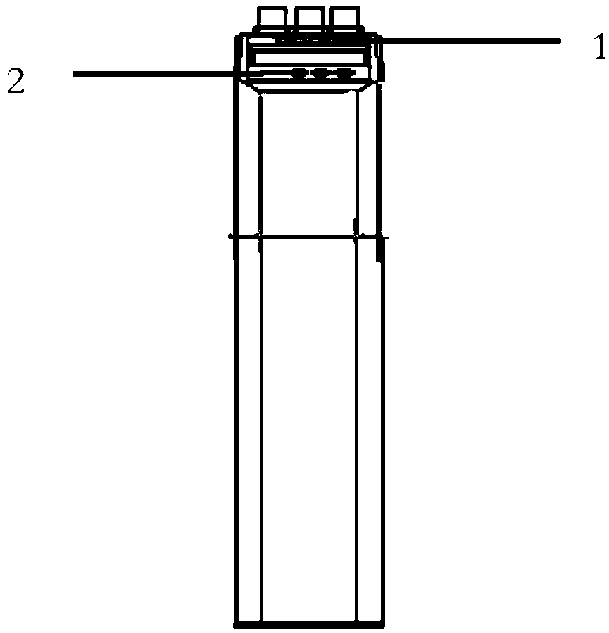
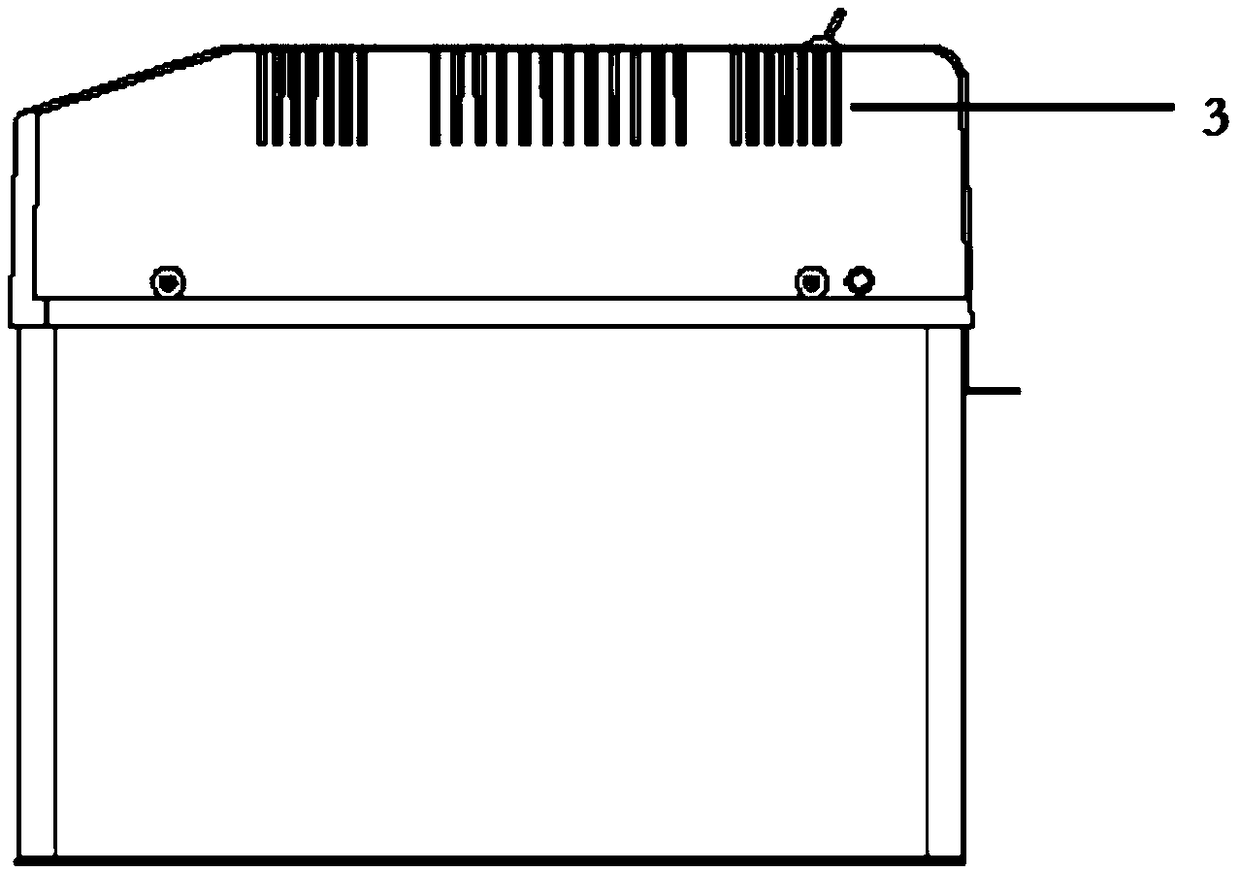
[0050] The invention relates to a shell of a power capacitor compensation device, such as figure 1 As shown, the circular hole on the upper part of the display part is the position of the indicator light 1, and the circular and square hole on the lower part of the display part is the position of the control button 2. Such as figure 2 and 4 As shown, there are vertical strip-shaped cooling slots 3 on both sides of the outer casing of the power capacitor compensation device, as shown in image 3 and 5 As shown, the 55mm*46mm opening at the upper end of the casing tail is used to install the miniature circuit breaker 4, and the rear end of the opening of the miniature circuit breaker 4 has three oval openings with a distance of 18mm to facilitate the screwdriver to enter and tighten when the external power supply line is connected to the miniature circuit breaker. screw. There are three openings of 8mm*13mm in the upper part of the rear end of the cover. From left to right, ...

Embodiment 2

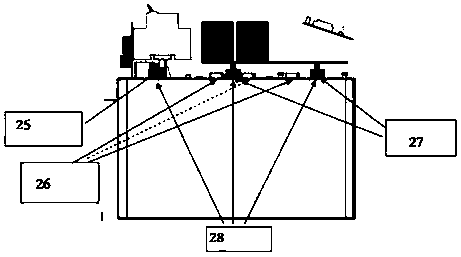
[0076] Such as Figure 6 and 8 As shown, this intelligent compensation terminal is a three-phase co-compensation compensation device. The optional capacity of the co-compensation capacitor body is 2.5Kvar-40Kvar, and each phase can independently compensate reactive power. Installed in the complete set of cabinets in the distribution transformer area according to the load ratio to form a centralized compensation of reactive power in the low-voltage power grid. The control system hardware includes a main board 21, a function board 18 and a switch board 23. Among them, the switch board used for capacitor switching is vertically fixed on the main board in the form of upper and lower rows, and the function board is vertically fixed at the tail of the capacitor board to ensure the maximum utilization of space. At the same time, the strong current and weak current signals are respectively arranged on the front and rear sides of the motherboard, and a safe distance should be ensured....

Embodiment 3

[0078] Such as Figure 4 and 9 As shown, the terminal shell is divided into the black injection molding part on the capacitor body and the capacitor upper cover. The capacitor body and the upper cover of the capacitor are fixed by screws around the capacitor, and the black injection molded parts on the body are supported by copper pillars to fix the control unit circuit board and capacitor. The front layout of the shell mainly includes windows such as liquid crystal display, button 2, indicator light 1, and miniature circuit breaker 4. The rear part includes two RJ45 interfaces, three-phase four-wire interfaces, and external current measurement terminal interfaces. The round hole on the left side is the N-phase terminal. interface. Vertical strip-shaped slot holes are opened on both sides of the upper cover to ensure the heat dissipation of the capacitor. The total size of the upper cover (length*width*height) is 345mm*78mm*100mm, and it is installed directly above the capa...


PUM


Abstract

The invention relates to a housing of a power capacitor compensation device, comprising a modular fixed support frame of a capacitor body and an independent capacitor body outer cover. The modular fixed support frame of the capacitor body comprises a circuit board fixing seat, three-phase four (three) line connecting terminals, a micro circuit breaker supporting frame and a capacitor body outer cover fixing seat. The independent capacitor casing is an ABS material integrated casing, A longitudinal inn edge of that shell of the power capacitor compensation device is provide with a boss, At thatend of the shell of the power capacitor compensation device, a clamping groove is arranged to fix the circuit functional board, so that the lateral force deformation of the shell of the power capacitor compensation device can be reduced, and the lateral or longitudinal shock and vibration generated to the functional board during installation or transportation can be cushioned at the same time. The power capacitor shell of the invention has the characteristics of light weight, smooth surface, modularization, heat resistance, difficult deformation and the like.

Description

technical field [0001] The invention relates to a shell of a power capacitor compensation device in the field of reactive power compensation. Background technique [0002] With the rapid advancement of the country's urbanization process, a large number of residential buildings, high-end shopping malls, hotels, offices and other civil buildings have sprung up in cities, and urban electricity consumption has also increased rapidly. However, most of these civil construction sites use single-phase inductive loads, resulting in a seriously low power factor of the low-voltage power grid and a seriously large reactive power line loss. This is not compatible with the country's current policy of "energy saving, emission reduction, green environmental protection". The use of reactive power compensation is an effective way to improve power quality, tap the potential of the power grid, and reduce line losses. [0003] Reactive power problems generally exist in the five links of "gener...

Claims


Application Information

Patent Timeline
Patent Type & Authority Applications(China)
IPC IPC(8): H02B1/26H02B1/04H02J3/18
CPCH02B1/04H02B1/26H02J3/18Y02E40/30
Inventor 唐明群顾自立郑陈凯吴俊峰沈玉鑫薛秋香刘娜沙凯旋
Owner NANJING KEWO ELECTRIC POWER TECH
Why Eureka
Try Eureka