
Overhead rail type feed conveying device

A conveying device and track-type technology, which is applied in the field of livestock and poultry breeding, can solve the problems of large power consumption, difficulty in ensuring the level, and increased conveying resistance, and achieve the effects of strong terrain adaptability, shortened feeding time, and large blanking outlet

Active Publication Date: 2019-01-08
CHINA AGRI UNIV
View PDF7 Cites 5 Cited by
  • Summary
  • Abstract
  • Description
  • Claims
  • Application Information

AI Technical Summary

Problems solved by technology

When conveying the material, the screw or plug plate (or scraper) is attached to the inner wall of the pipe to rotate or move in one direction, and the feed is pushed to the outlet above the trough and then automatically dropped into the trough. These two conveying methods can realize dry Automatic conveying and distributing of feed, but there are the following defects and problems: 1) When adopting the pipeline screw conveying method, each row of pens needs to be equipped with a pipeline screw conveying system, and the investment and use costs of the conveying equipment are relatively high; (or scraper) mode, the adjacent fence pipes need to be connected in series through the corner plate and the straight pipe, the pipeline transmission line is long, there are many turns, the resistance is large, the supporting power is large, and the use cost is high; 2) The long material line requires multi-section pipelines Splicing installation requires high installation requirements, and it is difficult to ensure the level. Grooves are prone to appear at the joints of the pipes, and it is easy to cause the screw or plug disc (or scraper) to move against the bottom wall of the pipe and get stuck, increasing the conveying resistance, and the pipe wall is easy to be worn. , the service life of the system is not long, and maintenance is difficult; 3) The steel cable or chain connected to the plug plate (or scraper) is subjected to a large force during use, and is prone to deformation, elongation or fracture, which affects the operation and reliability of the system; 4 ) in the pipeline transportation, the pellet feed is easily crushed to form powder, because there is always a place where the screw or plug plate (or scraper) does not contact with the pipe wall and there is a groove between two adjacent pipes, the powder cannot be real-time It is pushed and remains in the pipeline, which is difficult to clean up and easily contaminates fresh feed; 5) When the amount of feed conveyed in the pipeline is large, it is easy to cause blockage and large power consumption; Feed transportation of the whole system; 7) The pipeline is only suitable for transporting dry feed, not suitable for transporting green feed mixture and feed with high water content, because the feed sticks to the pipe wall and remains, so it must be cleaned after each feeding, which increases the cost of use ; 8) On the pipeline conveying system, if it is necessary to distribute quantitatively to each trough, it is necessary to add a set of feeding control and metering device above each trough, which is large in quantity and high in cost; 9) Pipeline conveying system The material can only be conveyed in order, and the front trough is filled with material before going to the next trough. Due to the small diameter of the conveying pipe, it takes a long time to complete all the troughs in the house, and it is difficult to achieve simultaneous feeding in the same house. 10) At present, pipeline feed transportation is mostly used in the house, and the application outside the house is only used for the short-distance outdoor storage tower to feed the indoor storage box, and between the feed warehouse and the outdoor storage tower. Due to the long distance and the influence of the terrain, the feed transportation system of the pipeline is complicated, so it is rarely used.

Method used


Image

  • Overhead rail type feed conveying device
  • Overhead rail type feed conveying device
  • Overhead rail type feed conveying device

Examples


Embodiment Construction

[0049] The present invention will be further described below in conjunction with the accompanying drawings.

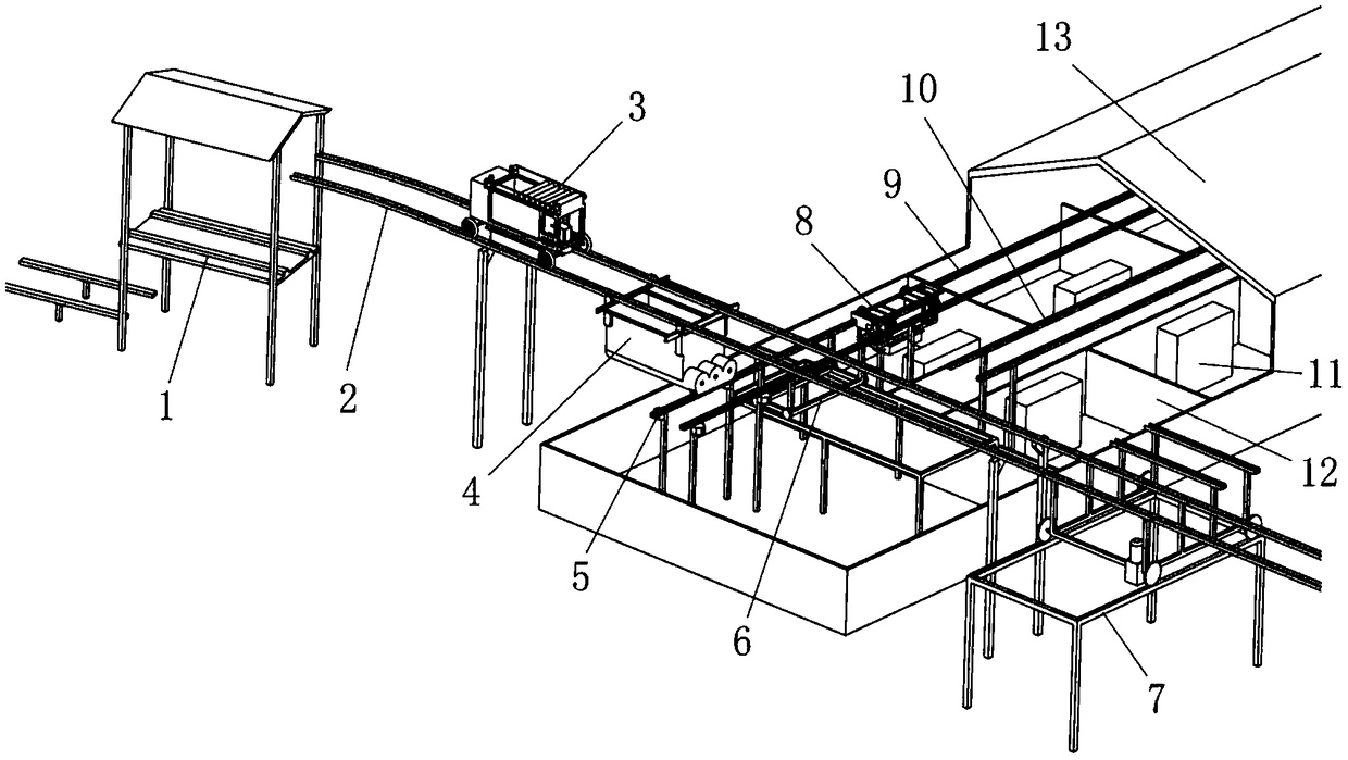
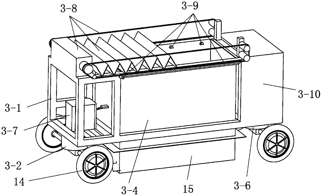
[0050] Such as figure 1 with figure 2 As shown, the embodiment of the present invention includes: a central control system, a lifting track mechanism 1 outside the pig house 13, a feeding track 2, a feeding car 3, a transfer warehouse 4 and an avoidance track mechanism 7, and a weighing platform 5 in the pig house 13 , track translation mechanism 6, distribution cart 8, first row of distribution rail 9, second row of distribution rail 10 and collection type trough 11; wherein the feeding cart 3 moves on the feeding rail 2, and the transfer warehouse 4 is hoisted on the feeding rail 2 Located at the bottom of the pig house 13, a weighing platform 5 that is also located in the pig house 13 is installed under the transfer warehouse 4. The side of the weighing platform 5 facing the pen 12 is provided with a rail translation mechanism 6, and the rail translation mechanism...


PUM


Abstract

The invention discloses an overhead rail type feed conveying device belonging to the field of livestock and poultry breeding. A feed track runs through a pigsty, a material feed cart moves on the feedtrack, a transfer bin is hoisted under the feeding track in the pigsty, a weighing platform is also located in the pigsty is installed under the transfer bin, a first-row feed distribution track anda second-row feed distribution track which do not interfere with each other are arranged on one side of a track translation mechanism toward the pigpens, and aggregate food troughs are arranged in several pigpens below the first-row feed distribution track and the second-row feed distribution track; the feeding rail is provided with an interrupting part at any straight part outside the pigsty, andan avoiding rail mechanism is installed at the relative position of the interrupting part. Compared with the traditional pipeline conveying, the invention has the problems that the pipeline is easy to be worn, easy to be broken down, difficult to be repaired and maintained, the residual feed in the pipeline is not easy to be cleaned, and the conveying system of the rail car works more reliably, is easier to be used and maintained, and has longer service life.

Description

technical field [0001] The invention belongs to the technical field of livestock and poultry breeding, and in particular relates to an elevated track type feed conveying device. Background technique [0002] At present, pig houses in large-scale pig farms generally adopt the form of double-row or multi-row pens. The number of pens is large and the stocking density is high. Daily feeding is a repetitive and heavy labor. In recent years, with the increase in labor costs and feed costs The traditional manual feeding method is no longer suitable for actual production needs, and there is an urgent need for mechanized and automated feeding equipment to improve feeding efficiency and feeding benefits. At present, the mechanized feeding in the actual breeding production is mainly reflected in the feed conveying mode, and the most widely used are the pipeline shaftless screw conveying mechanism and the pipeline plug disc (or scraper) conveying mechanism. When conveying the material,...

Claims


Application Information

Patent Timeline
IPC IPC(8): A01K5/02B65G35/00
CPCA01K5/0275A01K5/0291B65G35/00
Inventor 庞昌乐程进陈刚李保明
Owner CHINA AGRI UNIV
Learn More