
Oil slick collector and oil slick collecting method

A collector and oil slick technology, which is applied in chemical instruments and methods, separation methods, grease/oily substance/float removal devices, etc., can solve the problems of inefficient and clean oil-water separation, achieve efficient oil slick collection work, strengthen The effect of cleanliness and improved precision

Pending Publication Date: 2019-01-08
江苏旭龙环境科技有限公司
View PDF0 Cites 0 Cited by
  • Summary
  • Abstract
  • Description
  • Claims
  • Application Information

AI Technical Summary

Problems solved by technology

[0003] One of the purposes of the present invention is to solve the problem that the oil-water separation in the prior art is not efficient enough and clean

Method used


Image

  • Oil slick collector and oil slick collecting method
  • Oil slick collector and oil slick collecting method
  • Oil slick collector and oil slick collecting method

Examples


Embodiment 1

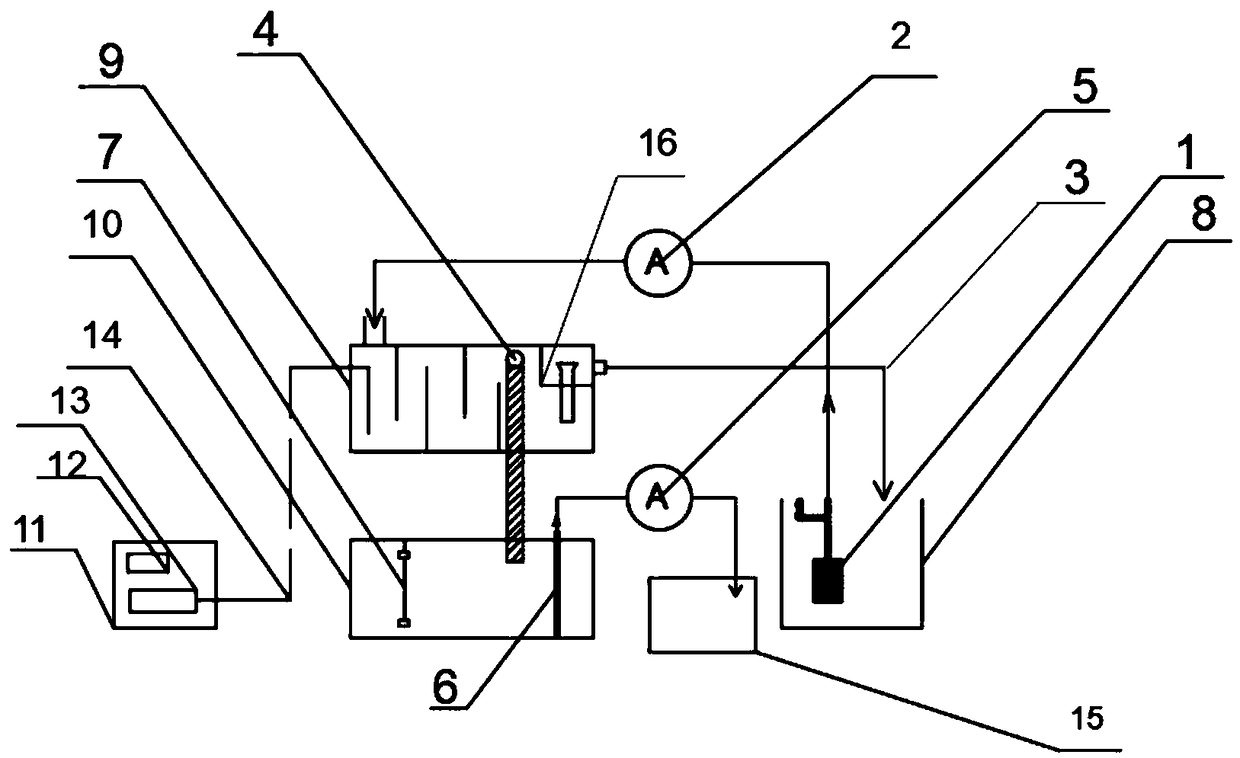
[0042] like figure 1As shown, a floating oil collector 1 includes a water inlet diaphragm pump 2, and the water inlet diaphragm pump 2 is provided with an oil-water separation box 9, an oil outlet pipe 4, a water outlet pipe 3, an oil separation tank 16, a waste water tank 8, and a floating oil tank. Oil collection buoy, collecting waste oil tank 10. Wherein, the floating oil collection buoy is set in the waste water tank 8, the two ends of the water inlet diaphragm pump 2 are connected to the oil-water separation box 9 and the oil floating collection buoy, the oil outlet pipe 4 and the oil separation chamber 16 are arranged in the oil-water separation box 9, and the water outlet pipe 3 Both ends are connected to the waste water pool 8 and the oil separation tank 16, and the oil outlet pipe 4 is connected to the waste oil tank 10 for collecting. First start the water-inlet diaphragm pump 2, and directly suck the waste liquid of the oil-water mixture in the waste water pool 8 ...

Embodiment 2

[0061] A method for collecting slick oil, comprising the following steps:

[0062] Collect the oil slick, start the water inlet diaphragm pump 2, and use the oil slick collection buoy 1 to directly extract the oil slick in the waste water tank 8 into the oil-water separation tank 9;

[0063] Sterilization, start the ozone generator 13, and the generated ozone enters the oil-water separation box 9 along the delivery pipe 14 to effectively sterilize the oil and water;

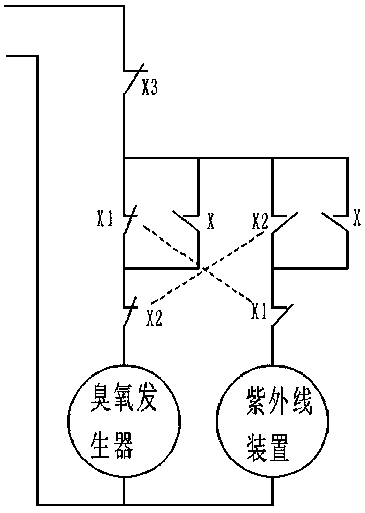
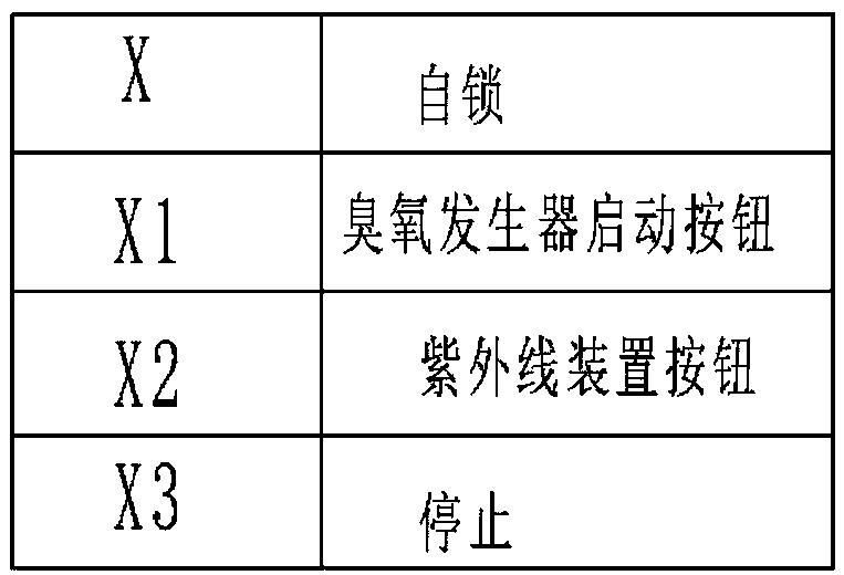
[0064] Switch the sterilization device, according to the requirements of the ozone concentration, the ozone sensor transmits the information to the circuit control system, if the standard is met, the ozone generator 13 continues to operate, if not, then switch to the ultraviolet sterilization device for effective sterilization;

[0065] Water separation, when the oil and water in the oil-water separation tank 9 reach a certain height, the oil separation chamber 16 isolates the floating oil, and then the water in ...


PUM


Abstract

The invention discloses an oil slick collector, and relates to the technical field of efficient collection and purification of oil slick. The oil slick collector comprises an inlet water diaphragm pump, wherein an oil and water separating tank, an oil outlet pipe, a water outlet pipe, an oil separating bin, a wastewater tank, an oil slick collecting buoy and a waste oil collecting tank are arranged at the downstream of the inlet water diaphragm pump; the oil slick collecting buoy is arranged inside the wastewater tank; the two ends of the inlet water diaphragm pump are communicated with the oil and water separating tank and the oil slick collecting buoy; the oil outlet pipe and the oil separating bin are arranged inside the oil and water separating tank; the two ends of the water outlet pipe are communicated with the wastewater tank and the oil separating bin; the oil outlet pipe is communicated with the waste oil collecting tank. The oil slick collector is easy and convenient to operate; firstly, during oil slick collection, oil slick can be directly extracted, so that water extraction is reduced, the thickness of the oil slick covering an orifice of the oil outlet pipe is increased, efficient oil slick collecting operation is performed and the cleanliness during oil and water separation is improved; finally, a filtrate separated by the oil and water separating tank is returned to the wastewater tank for repeated treatment, so that the separating accuracy is greatly improved.

Description

technical field [0001] The invention relates to the technical field of efficient collection and purification of oil slicks, in particular to an oil slick collector. Background technique [0002] Oil slick collector is a commonly used water treatment equipment with high oil content in industry, and it is widely used in oil field, catering, chemical industry, refinery, machining and other industries. Oil and water are immiscible liquids, and the oil floats on the water surface. According to the needs of national environmental protection and factory technology, the two must be separated. The mechanical structure used in the separation of oil and water in the existing oil removal device cannot repeatedly collect and process the oil and water, and both oil and water are flowing liquids. When the oil flows, the water will easily move with the flow of the oil, resulting in The oil-water separation is not clean enough, and when the oil slick is collected in the existing oil removal...

Claims


Application Information

Patent Timeline
IPC IPC(8): C02F1/40C02F9/04C02F9/08
CPCC02F1/40C02F1/50C02F1/78C02F9/00C02F2303/04C02F2301/08C02F1/32
Inventor 惠毓杰曹静芳贾红宇
Owner 江苏旭龙环境科技有限公司
Learn More