Wide-angle lens and panoramic photography system

A wide-angle lens and lens technology, which is applied in the field of wide-angle lens and panoramic camera system, can solve the problems of high processing difficulty, short time, and inability to correct high-order aberrations well, and achieve the effect of small overall length, processing difficulty and cost reduction

Active Publication Date: 2019-01-08
合肥联创光学有限公司
View PDF5 Cites 3 Cited by
  • Summary
  • Abstract
  • Description
  • Claims
  • Application Information

AI Technical Summary

Problems solved by technology

At present, 360° panoramic high-definition cameras have entered the market for a relatively short period of time, and are still in the development period of market potential. At the same time, the lenses used in panoramic camera systems on the market are mostly spherical lenses, which cannot correct high-order aberrations well.
Some technical solutions provide a wide-angle lens without blind spots. Although the field of view reaches 270°, it still does not meet the needs of panoramic photography, and the resolution quality is low and the processing is difficult. It is no longer suitable for the current market environment.

Method used


Image

  • Wide-angle lens and panoramic photography system
  • Wide-angle lens and panoramic photography system
  • Wide-angle lens and panoramic photography system

Examples


no. 1 example

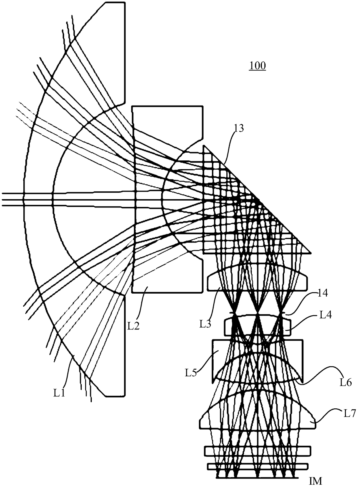
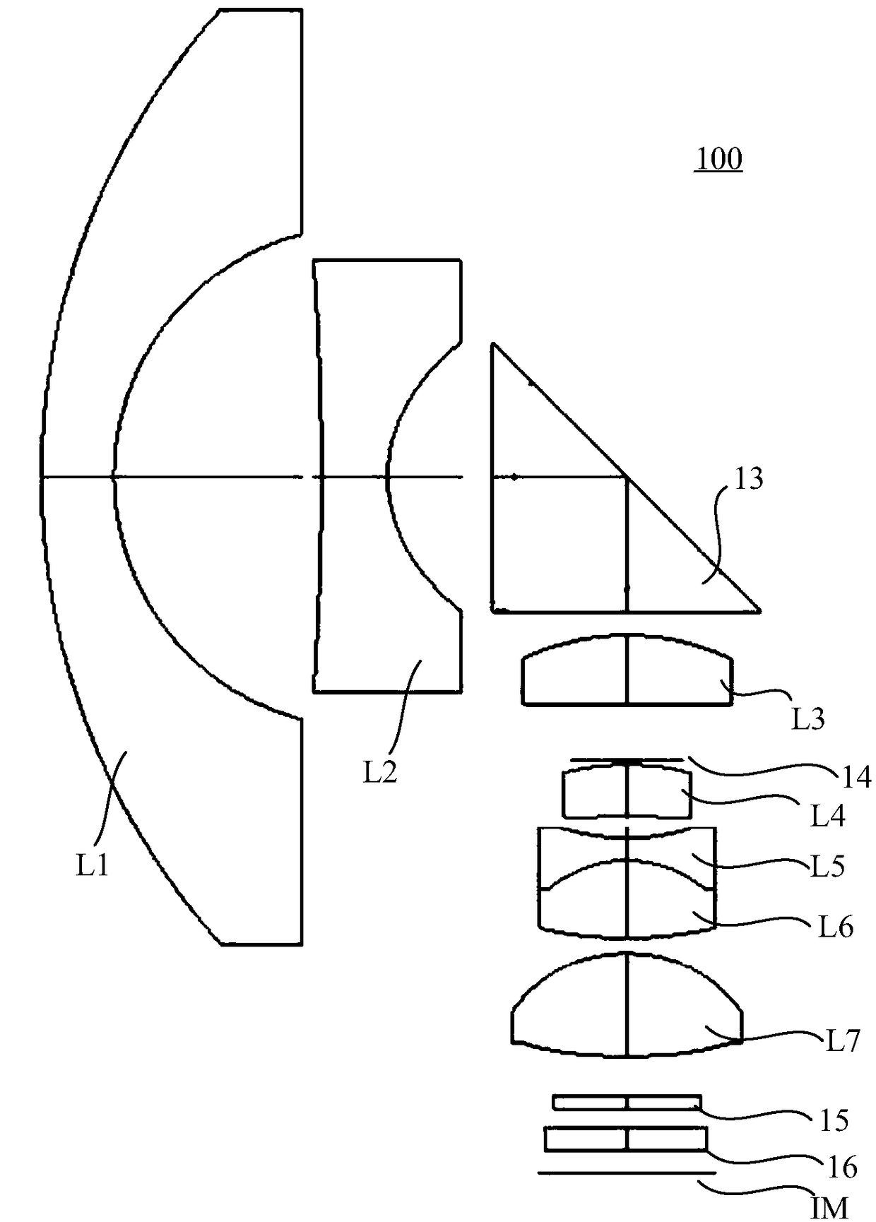
[0027] see figure 1 The wide-angle lens 100 provided by the first embodiment of the present invention includes a first lens L1, a second lens L2, a third lens L3, a fourth lens L4, a fifth lens L5, and a sixth lens in order from the object side to the imaging surface IM. L6 , the seventh lens L7 and the reflective element 13 .

[0028] The first lens L1 has negative refractive power, and the image-side surface is concave, and the first lens L1 is a spherical mirror in a meniscus shape. The first lens L1 can be a glass lens with a higher refractive index. The high refractive index material can achieve fast light collection, reduce the inclination angle of the image-side surface of the first lens L1, and reduce the processing cost.

[0029] The second lens L2 has negative refractive power, and the image-side surface is concave.

[0030] The third lens L3 has positive refractive power and is a spherical mirror.

[0031] The fourth lens L4 has positive refractive power, and the...

no. 2 example

[0093] see Image 6 , shows a structural diagram of a wide-angle lens 200 provided in this embodiment. The wide-angle lens 200 of the present embodiment is substantially the same as the wide-angle lens 100 of the first embodiment, except that the Abbe numbers of the fifth lens L5 and the sixth lens L6 of the wide-angle lens 200 of the present embodiment are different, and the effect on chromatic aberration The ability to compensate is different. Specific lens-related parameters of each lens are shown in Table 3.

[0094] table 3

[0095]

[0096] Please refer to Table 4, which shows the parameters related to the aspheric surface of each lens in this embodiment.

[0097] Table 4

[0098]

[0099]

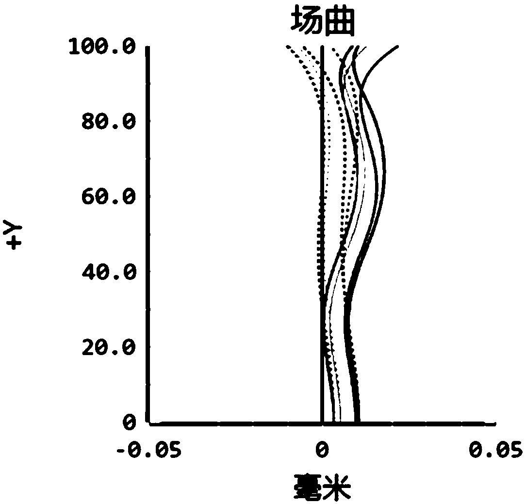
[0100] The field curvature and F-Theta distortion curves of the wide-angle lens 200 provided in this embodiment are as follows: Figure 7 with Figure 8 As shown, it can be seen from the figure that the field curvature and distortion of the wide-angle lens 200 are well...

no. 3 example

[0102] see Figure 10 , shows a schematic diagram of the structure of a wide-angle lens 300 provided in this embodiment. The wide-angle lens 300 in this embodiment is roughly the same as the wide-angle lens 100 in the first embodiment. The chief ray angle has a different effect. Specifically, the stop 14 is located between the fourth lens L4 and the fifth lens L5.

[0103] Please refer to Table 5, which shows parameters related to each lens of the wide-angle lens 300 in this embodiment.

[0104] table 5

[0105]

[0106]

[0107] Please refer to Table 6, which shows the parameters related to the aspheric surface of each lens in this embodiment.

[0108] Table 6

[0109]

[0110] The field curvature and F-Theta distortion curves of the wide-angle lens 300 provided in this embodiment are as follows: Figure 11 with Figure 12 As shown, it can be seen from the figure that the field curvature and distortion of the wide-angle lens 300 are well corrected. Figure 13 ...


PUM

PropertyMeasurementUnit
Total lengthaaaaaaaaaa
Diagonal lengthaaaaaaaaaa

Abstract

The invention provides a wide-angle lens. From an object side to an imaging surface, the wide-angle lens orderly comprises a first lens, a second lens, a third lens, a fourth lens, a fifth lens, a sixth lens, a seventh lens and a reflective element which is arranged between the second lens and the third lens, wherein the first lens has negative focal power, and an image side surface of the first lens is a concave surface; the second lens has negative focal power, and the image side surface of the second lens is the concave surface; the third lens has positive focal power; the fourth lens has positive focal power, and the image side surface of the fourth lens is the concave surface; the fifth lens has negative focal power, and the image side surface and an object side surface of the fifth lens both are the concave surfaces; the sixth lens has positive focal power, and the image side surface and the object side surface of the sixth lens both are the convex surfaces; the seventh lens haspositive focal power, and the image side surface and the object side surface of the sixth lens both are the convex surfaces; the first lens and the third lens are spherical mirrors, one of the secondlens and the fourth lens is an aspherical mirror and the other one thereof is the spherical mirror; the fifth lens and the sixth lens both are the spherical mirrors, moreover, the fifth lens and the sixth lens are integrated together, and the seventh lens is the aspherical mirror. The invention also provides a panoramic photography system.

Description

technical field [0001] The invention relates to the technical field of optical lenses, in particular to a wide-angle lens and a panoramic camera system. Background technique [0002] With the continuous improvement of the market environment for panoramic lenses, panoramic high-definition photography lenses have become more and more diverse. At present, 360° panoramic high-definition cameras have entered the market for a short period of time and are still in the market potential development period. At the same time, the lenses used in panoramic camera systems on the market often use spherical lenses, which cannot correct high-order aberrations well. Some technical solutions provide wide-angle lenses without blind spots. Although the field of view reaches 270°, it still does not meet the needs of panoramic photography, and the resolution quality is low and processing is difficult, which is no longer suitable for the current market environment. [0003] In order to meet the ne...

Claims


Application Information

Patent Timeline
IPC IPC(8): G02B13/00G02B13/06
CPCG02B13/0045G02B13/06G02B13/0065G02B9/64G02B13/006
Inventor 李伟娜高博韩建曾吉勇
Owner 合肥联创光学有限公司
Why Eureka
Try Eureka