Cable joint protective clip and cable joint protective clip assembly

A cable joint and protective clip technology, applied in the direction of connecting/terminating cable equipment, etc., can solve the problems of poor cable joint contact, increased power outage time, low work efficiency, etc., to reduce the probability of equipment tripping and other events, high Safety in use and convenient insulation effect

Pending Publication Date: 2019-01-08
GUANGZHOU BUREAU CSG EHV POWER TRANSMISSION
View PDF0 Cites 3 Cited by
  • Summary
  • Abstract
  • Description
  • Claims
  • Application Information

AI Technical Summary

Problems solved by technology

However, the way of using insulating tape to wrap the disassembled cable joints has the following disadvantages: (1) low safety and reliability, the way of wrapping the insulating tape is limited by the working environment and conditions, and the on-site working environment is often in a narrow In the mechanism box or control box, and the cable joints have high hardness and short length, it is difficult to implement high-quality wrapping. At the same time, the cable joints wrapped with insulating tape are prone to AC current after they are touched and squeezed during operation. Connecting in series to the low-voltage DC system will cause tripping of equipment and affect the safety of power supply; (2) The work efficiency is low and cannot meet the needs of fast power supply during high-load periods; in the maintenance work of substations, it often takes dozens of components to replace Cable joints need to be bandaged, but with insulating tape, it usually takes a few minutes to bandage and remove a single cable joint, and it takes several hours for dozens of cable joints to bandage and remove the bandage. Hours of power outage time may increase the risk of the power grid or limit the load in some areas during the peak period of power load; (3) The colloid that falls off from the insulating tape will adhere to the metal surface of the cable joint, resulting in poor contact of the cable joint, causing protection and refusal to move, etc. Consequences; (4) The insulating tape is a disposable plastic product, and long-term use will cause environmental pollution

Method used


Image

  • Cable joint protective clip and cable joint protective clip assembly
  • Cable joint protective clip and cable joint protective clip assembly
  • Cable joint protective clip and cable joint protective clip assembly

Examples


Embodiment 1

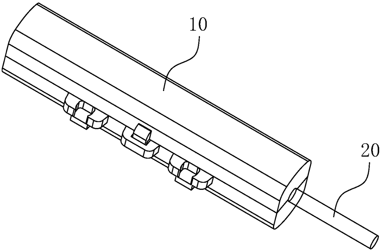
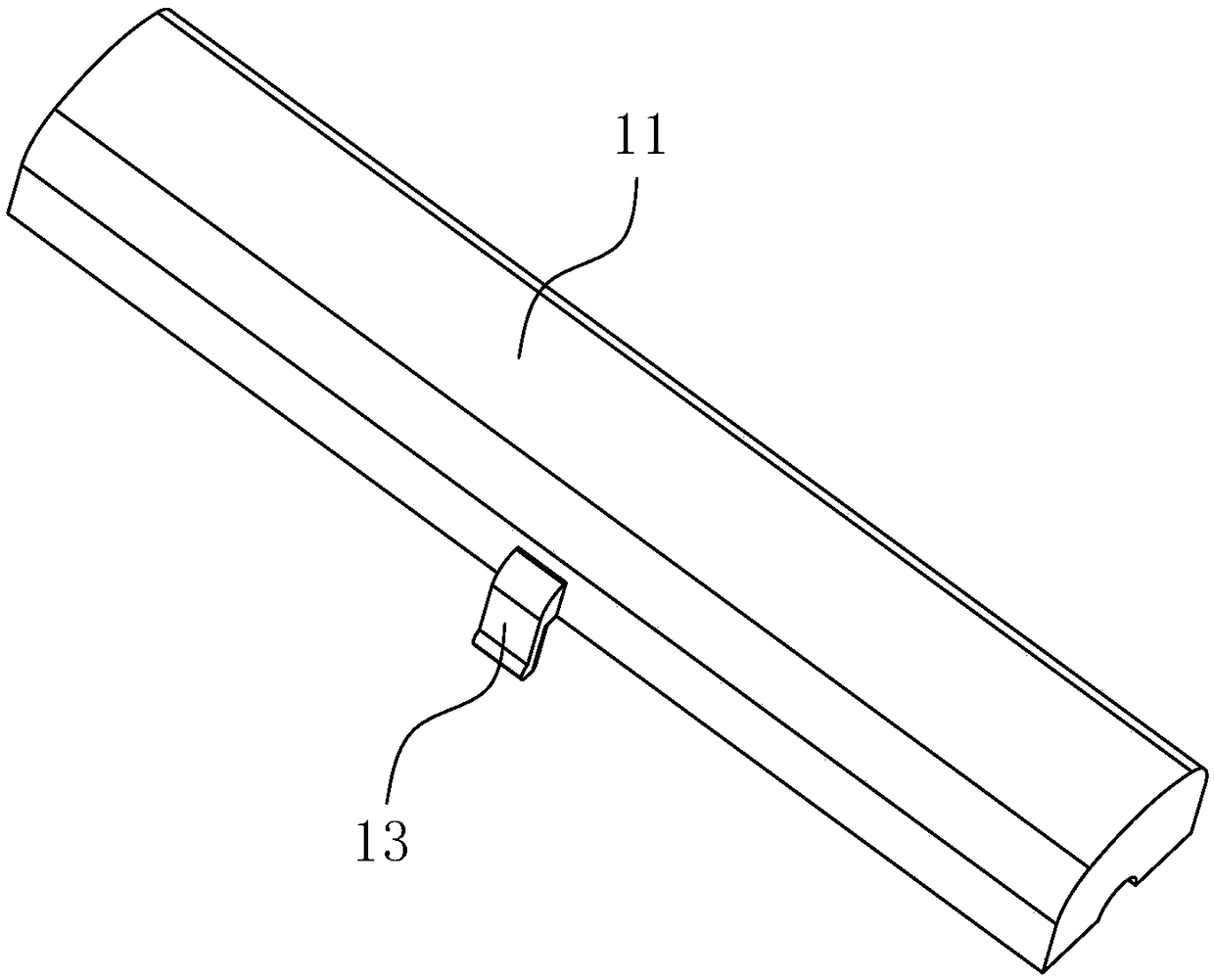
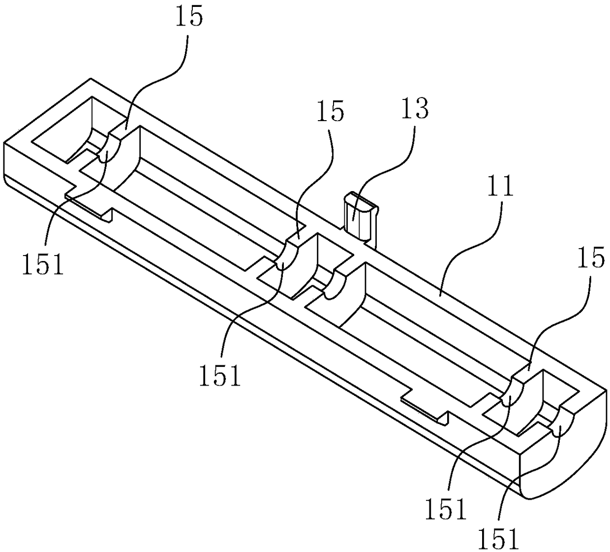
[0048] see Figure 1 to Figure 4 ,in, figure 1 It is a structural schematic diagram of the cable joint protection clamp 10 and the cable 20 according to the embodiment of the present invention, figure 2 with image 3 It is a structural schematic diagram of the first clip body 11 of the embodiment of the present invention, Figure 4 It is a schematic structural diagram of the second clip body 12 of the embodiment of the present invention.

[0049] The cable joint protection clip 10 of the embodiment of the present invention includes a first clip body 11 and a second clip body 12 .

[0050] The first clamping body 11 is matched with the second clamping body 12 , and the first clamping body 11 and the second clamping body 12 are opened and closed.

[0051] Both the first clamping body 11 and the second clamping body 12 are provided with a corresponding clamping structure, and the clamping structure is used to clamp the cable connector.

[0052] Both the first clip body 11 a...

Embodiment 2

[0083] see Figure 1 to Figure 5 ,in, Figure 5 It is a structural schematic diagram of the cable joint protective clip assembly of the embodiment of the present invention.

[0084] The cable joint protection clamp assembly of the embodiment of the present invention includes a plurality of the aforementioned cable joint protection clamps 10 .

[0085] The cable joint protection clip 10 includes a first clip body 11 and a second clip body 12 .

[0086] The first clamping body 11 is matched with the second clamping body 12 , and the first clamping body 11 and the second clamping body 12 are opened and closed.

[0087] Both the first clamping body 11 and the second clamping body 12 are provided with a corresponding clamping structure, and the clamping structure is used to clamp the cable connector.

[0088] Both the first clip body 11 and the second clip body 12 are made of insulating materials.

[0089] A plurality of cable joint protective clips 10 are arranged side by side...


PUM


Abstract

The invention provides a cable joint protective clip and a cable joint protective clip assembly. The cable joint protective clip comprises a first clip body and a second clip body. The first clip bodyis matched with the second clip body, and the first clip body and the second clip body are opened and closed. The first clip body and the second clip body are provided with corresponding clip wire structures, and the clip wire structures are used for clamping the cable joints; The first clip body and the second clip body are made of insulating material. As that cable connector protective clip ofthe invention has high use safety, The utility model can be quickly used for insulating and clamping the disassembled cable connector, and the clamping effect is good, and the disassembled cable connector can be well protected; meanwhile, the disassembling of the cable connector clamping is convenient, the working efficiency of the overhaul operator is effectively improved, and the probability oftripping of the equipment and other events is greatly reduced.

Description

technical field [0001] The invention relates to the technical field of cable joint protection equipment, in particular to a cable joint protection clamp and a cable joint protection clamp assembly. Background technique [0002] In the maintenance work of the power industry, it is often necessary to disassemble and connect the cable joints. The disassembled cable joints are usually bare metal conductors, and in order to ensure the safety of the work, it is often necessary to insulate and wrap the exposed cable joints. After the work is completed It will be necessary to remove the insulation dressing of the cable joint and restore the original wiring. [0003] During the inspection and maintenance work, no corresponding insulation and bandaging measures are taken for the disassembled cable joints, or the insulation bandage of the dismantled cable joints is poor, which may easily cause equipment tripping and other events, affecting the safety of power supply. [0004] At prese...

Claims


Application Information

Patent Timeline
Patent Type & Authority Applications(China)
IPC IPC(8): H02G1/14
CPCH02G1/14
Inventor 查光年
Owner GUANGZHOU BUREAU CSG EHV POWER TRANSMISSION
Why Eureka
Try Eureka