An optical flow switching network scheduling method and an optical flow switching system

A technology of switching network and scheduling method, applied in the field of optical flow switching system and optical flow switching network scheduling, can solve the problems of reducing network channel utilization and throughput, increasing the average queuing delay, which cannot be ignored, etc. time, improve performance, and the effect of mature application conditions

Active Publication Date: 2019-01-08
SUNWAVE COMM
View PDF0 Cites 8 Cited by
  • Summary
  • Abstract
  • Description
  • Claims
  • Application Information

AI Technical Summary

Problems solved by technology

On the other hand, due to the internal blocking characteristics of the general network topology, the time it takes to reserve an available optical path is not negligible compared to the optical data stream transmission time (that is, the optical path maintenance time)
In the traditional optical flow switching scheduling method, the optical dat

Method used


Image

  • An optical flow switching network scheduling method and an optical flow switching system
  • An optical flow switching network scheduling method and an optical flow switching system
  • An optical flow switching network scheduling method and an optical flow switching system

Examples


Embodiment Construction

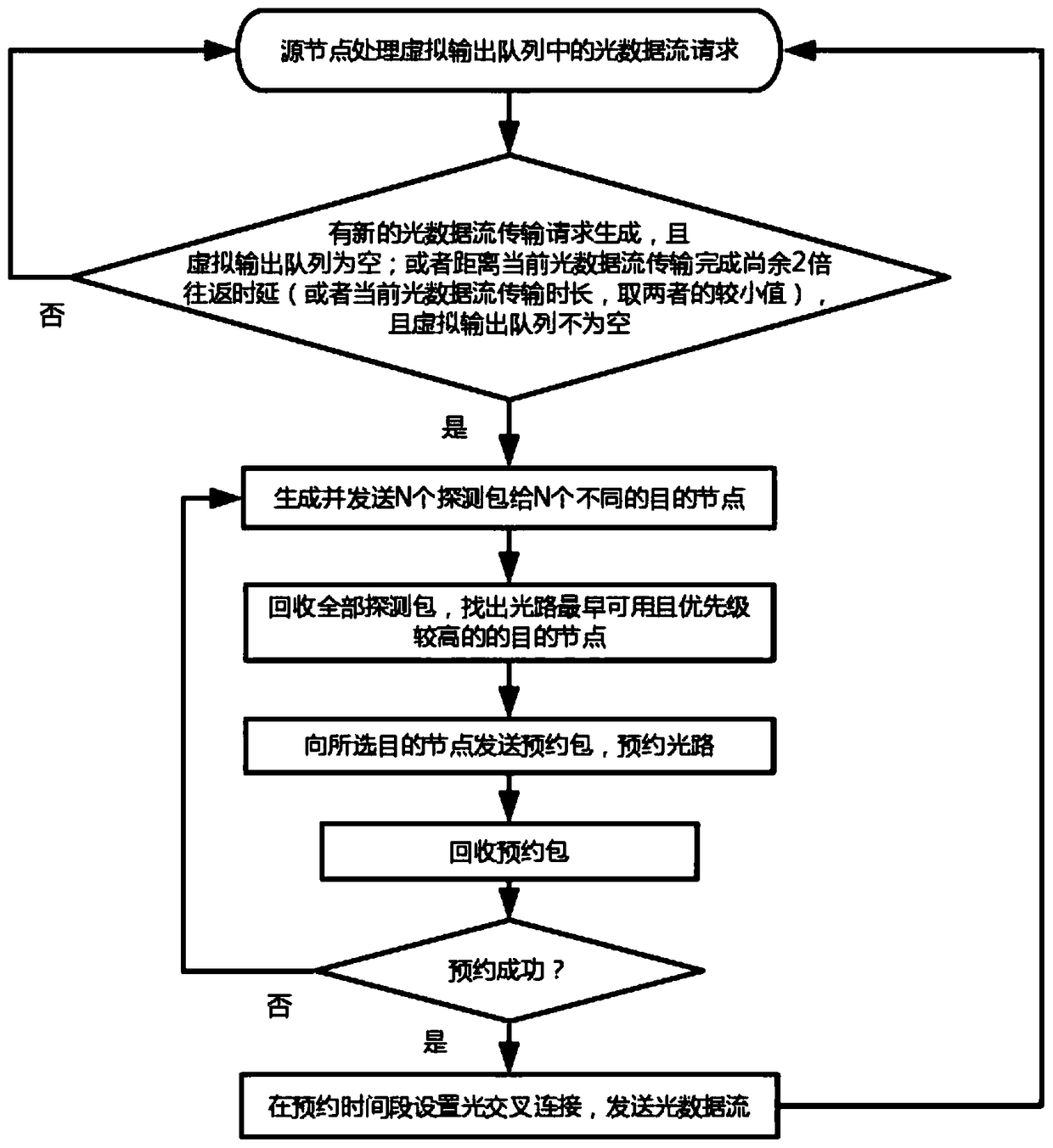
[0033] The gist of the present invention is in the distributed scheduling mode (that is, each source node independently establishes and releases the optical path, there is no centralized scheduling node) and the multi-purpose address detection technology (that is, detects multiple possible destination addresses simultaneously before setting up a channel each time) Based on the idea of ​​pipelining operations on the control plane and data plane, the optical path is reserved in advance for the optical data flow request at the front of the queue, shortening the head time of optical data flow transmission, and optimizing bandwidth utilization.

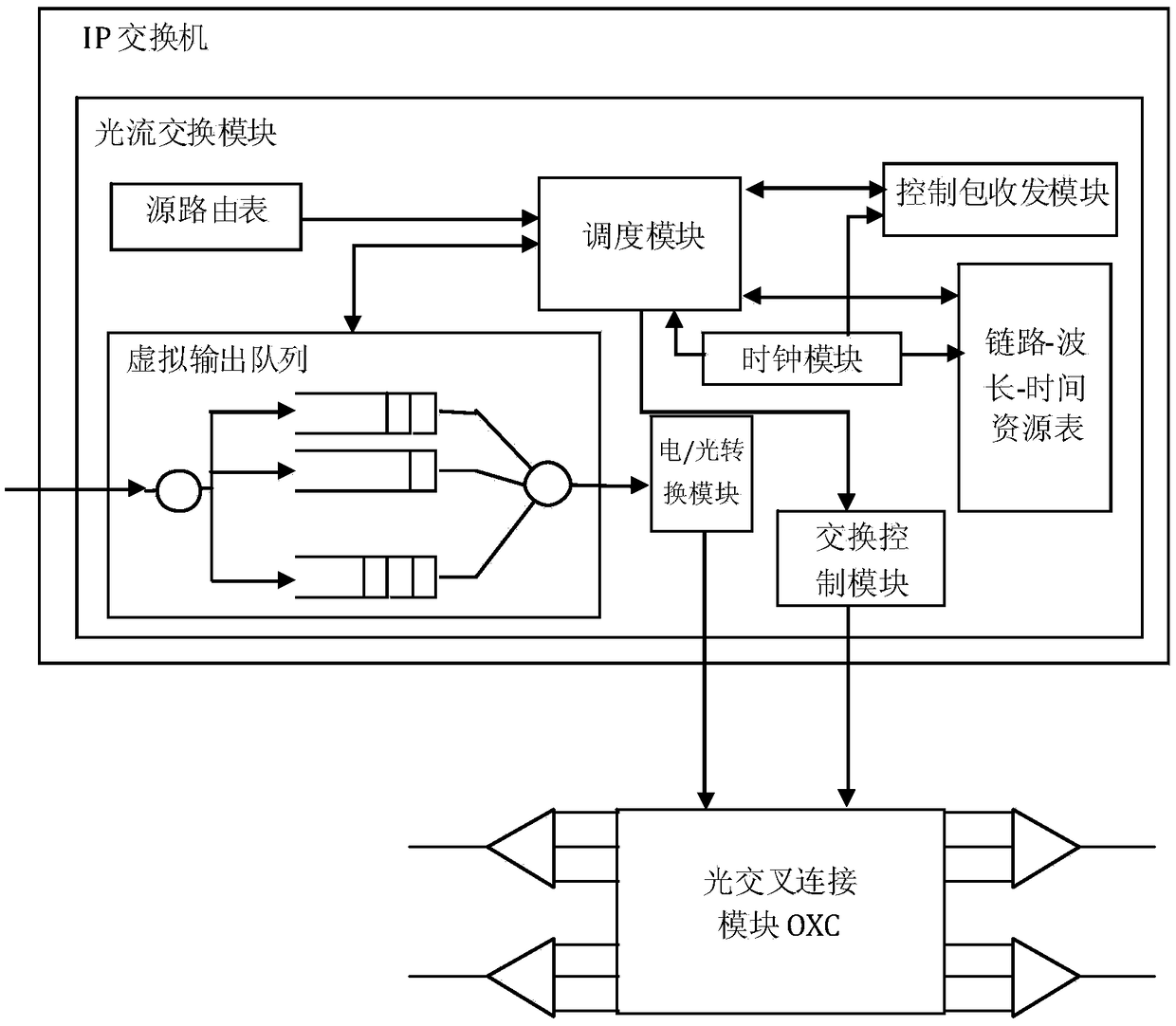
[0034] In order to make the object, technical solution and advantages of the present invention clearer, the embodiments of the present invention will be described in detail below in conjunction with the accompanying drawings. The system block diagram on which the present invention is based is as figure 1 , each node mainly consists of an I...


PUM


Abstract

The invention discloses an optical flow switching network scheduling method and an optical flow switching system. Each node in the system is mainly composed of an IP switch and an optical cross connection module. Each IP switch is provided with an optical flow switching module. The optical flow switching module comprises a virtual output queue and a link-wavelength-time resource table, source routing table, a scheduling module, a control packet transceiver module, an electronic/optical conversion module, a switching control module and a clock module. At the same time of transmitting optical data stream, the source node requests to start optical path reservation in advance for optical data stream in virtual output queue, detects the availability of optical paths corresponding to multiple destination nodes, combines queue head request priority and optical data stream transmission time, finds out the earliest available optical paths and reserves a time period for the optical paths. The invention has the following beneficial effects: 1, centralized scheduling nodes are not needed in the network, each node executes distributed scheduling, and the computational complexity is low; 2, thatoptical path schedule calculation and the data transmission are carried out simultaneously, the head time of the data transmission is shorten, the network throughput is improved, the average waitingtime of the queue is reduced, and the bandwidth utilization ratio is optimized; 3, adding time dimension to the scheduling allocation of link wavelength resources, which can improve the performance ofthe algorithm; 4, that device can be deploy based on the exist network equipment, and the application conditions are ripe.

Description

technical field [0001] The invention relates to an optical communication network, in particular to an optical flow switching network scheduling method and an optical flow switching system. Background technique [0002] Optical flow switching is a technology for next-generation all-optical switching networks. It is suitable for government departments, financial institutions, data centers, and telecom operators for end-to-end massive data high-speed transmission, data migration, and data disaster recovery. The basic idea of ​​optical flow switching is to dynamically establish a dedicated all-optical domain connection for each end-to-end data transmission (called optical data flow) request. The technical framework of the optical flow switching network is based on the existing network architecture, and each network node is composed of an IP switch and an all-optical switching node. The network control function and data forwarding function are logically decoupled into a control ...

Claims


Application Information

Patent Timeline
IPC IPC(8): H04Q11/00H04L12/865H04L47/6275
CPCH04L47/6275H04Q11/0005H04Q11/0062H04Q2011/0079
Inventor 钱正丰严军荣洪杭迪
Owner SUNWAVE COMM
Why Eureka
Try Eureka