Electromechanical device abnormal alarm stop control system and control method

A technology of electromechanical equipment and control system, which is applied in the direction of electric speed/acceleration control, chemical instruments and methods, mixers, etc., can solve problems such as reducing resistance torque, and achieve the effect of reducing damage, easy implementation and simple structure

Active Publication Date: 2019-01-11
南通志和电气有限公司
2 Cites 2 Cited by

AI-Extracted Technical Summary

Problems solved by technology

The existing electromechanical equipment is not equipped with an abnormal stop alarm system. In order to minimize losses, the present invention proposes an abnormal stop alarm control system and control method for electromechanical equipment, which can issue an alarm when the electromechanical...

Method used

In the described step 4 of above-mentioned technical scheme, set the rotating speed of stirring bar and the resistance value of potentiometer by speed knob, when setting rotating speed raises, then the resistance value of corresponding potentiometer reduces, in RC filter The RC time constant o...

Abstract

The invention discloses an electromechanical device abnormal alarm stop control system and a control method. The system comprises a UPS (Uninterrupted Power Supply), a Hall switch, an RC filter and acomparator, wherein the input end of the UPS is connected with the power grid; the output end of the UPS is connected with a switching power supply; the power input end of the Hall switch is connectedwith the output end of the switching power supply; the Hall switch is used for detecting the operating speed of a stirring rod on an electromechanical device; the input end of the RC filter receivesan output signal of the Hall switch; the RC filter comprises a capacitor and a resistor; the resistor is a potentiometer with an adjustable resistance value; a speed knob is arranged on the potentiometer; the rotating shaft of the speed knob is connected with the rotating shaft of the potentiometer; the power input end of the comparator is connected with the output end of the switching power supply; the inverting input end of the comparator is connected with the output end of the RC filter; the in-phase input end of the comparator is connected with a reference power supply; and the output endof the comparator is connected with the power end of a first alarm device. According to the system disclosed by the invention, the condition that the cost is greatly lost due to abnormal stop of the electromechanical device is avoided.

Application Domain

Transportation and packagingMixer accessories +3

Technology Topic

PotentiometerCapacitance +8

Image

  • Electromechanical device abnormal alarm stop control system and control method
  • Electromechanical device abnormal alarm stop control system and control method
  • Electromechanical device abnormal alarm stop control system and control method

Examples

  • Experimental program(1)

Example Embodiment

[0042] The present invention will be further described in detail below with reference to the accompanying drawings, so that those skilled in the art can implement it with reference to the text of the description.
[0043] It should be understood that terms such as "having", "including" and "including" used herein do not equate the presence or addition of one or more other elements or combinations thereof.
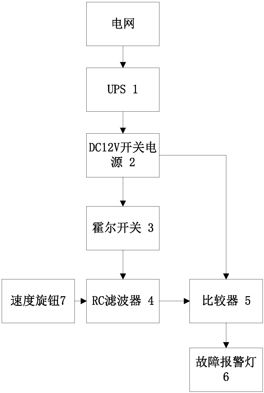
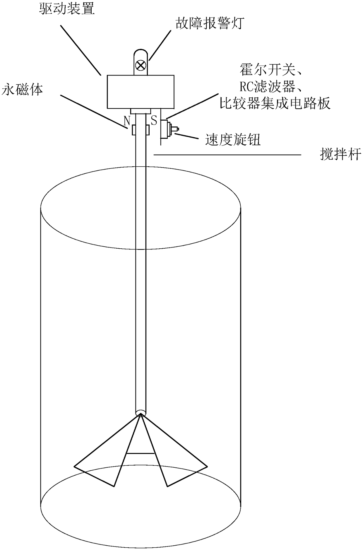
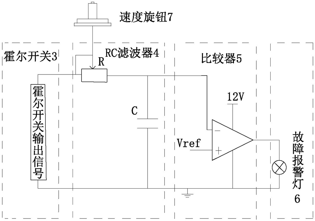
[0044] Such as Figure 1 to Figure 3 As shown, the present invention provides an alarm control system for abnormal stop of electromechanical equipment, including UPS1, DC12V switching power supply 2, Hall switch 3, RC filter 4, comparator 5, fault warning light 6, and speed knob 7.
[0045] The upper end of the electromechanical equipment is suspended and fixed to a driving device. Specifically, it can be fixed on the upper end of the electromechanical device by a support frame. A driving motor is provided in the driving device. The driving shaft of the driving motor is arranged vertically downward, and the top of the stirring rod Connect the drive shaft of the drive motor.
[0046] The input terminal of the UPS1 is connected to the power grid for charging, and the output terminal of the UPS1 is connected to the switching power supply 2 to continue to supply power to the alarm control system after the power supply from the power grid stops. The UPS1 and the switching power supply 2 are arranged in the driving device. The DC12V switching power supply 2 is used to provide the working power of the Hall switch 3, the comparator 5 and the entire circuit board. The Hall switch 3 is used to receive the magnetic field signal of the permanent magnet to detect the operating speed of the stirring rod, to determine the operating state of the stirring device, and to transmit the output signal to the RC filter 4.
[0047] The RC filter 4 processes the output signal of the Hall switch 3, and the output signal controls the comparator 5. The output signal of the comparator 5 controls the fault warning light 6. In the normal state, the fault warning light 6 is in the off state. When the equipment fails, the fault warning light 6 is controlled to give an alarm to notify the user in time to avoid damage to the equipment. Specifically, the inverting input terminal of the comparator 5 is connected to the output terminal of the RC filter 4, and the non-inverting input terminal of the comparator 5 is connected to a reference power supply. The reference power supply provides a reference voltage Vref. The reference voltage Vref Can be set according to requirements.
[0048] The RC filter 4 includes a capacitor C and a resistor R. The resistor R is a potentiometer with an adjustable resistance value. The potentiometer is provided with a speed knob. The rotation axis of the speed knob is connected to the potentiometer. The rotating shaft is connected to adjust the output resistance of the potentiometer.
[0049] Such as figure 2 As shown, the switching power supply is arranged at the upper end of the electromechanical equipment, the stirring rod is rotatably arranged at the lower end of the driving device, and a fault warning lamp is arranged on the top of the driving device so that the staff can quickly find it.
[0050] It also includes a first flip-flop and a second flip-flop. The signal input terminal of the first flip-flop is connected to the output terminal of the comparator 5, and the first output terminal of the first flip-flop is connected to a timer. The output terminal of the device is connected to a second flip-flop. The power terminal of the second alarm device is connected with the output terminal of the comparator through a programmable switch, and the programmable switch is connected with the output terminal of the second trigger. Among them, the comparator, the first flip-flop and the second flip-flop may all adopt the conventional parameter models in the prior art.
[0051] In this embodiment, a piece of permanent magnet is attached to the opposite sides of the top end of the stirring rod, and the two pieces of permanent magnet are placed in a mutually attracted manner. The Hall switch receives the magnetic field signal from the permanent magnet during the rotation to determine the rotation speed of the stirring rod.
[0052] A circuit board is arranged longitudinally outside the lower end of the driving device, and the Hall switch, RC filter, first trigger, second trigger, timer, telescopic controller and comparator are integrated on the circuit board, The speed knob is installed outside the circuit board to facilitate adjustment of the speed knob, and the speed knob is used to adjust the RC time constant in the RC filter.
[0053] Wherein, the stirring rod is a double-rod telescopic structure, the stirring rod includes a first rotating rod 21 with a hollow structure and a second rotating rod 22 provided with rotating blades, the first rotating rod 21 and the second rotating rod 22 rotates synchronously, the second rotating rod 22 is telescopically arranged at the lower part of the first rotating rod 21, the upper end of the first rotating rod 21 is connected with the drive shaft of the driving motor, and the inner top end of the first rotating rod 21 A telescopic mechanism 23 is provided, the telescopic end of the telescopic mechanism 23 is connected to the top of the second rotating rod 22, and the telescopic controller of the telescopic mechanism 23 is connected to the second output end of the first trigger.
[0054] Specific, such as Image 6 with 7 As shown, the first rotating rod 21 is a hollow structure, and a plurality of guide groove guide rails 211 are axially opened inside the first rotating rod 21. Correspondingly, the second rotating rod 22 is a solid shaft mechanism, and the outer side wall of the second rotating rod 22 A number of guide blocks 221 are protrudingly provided in the upper axial direction, and the guide blocks 221 are embedded in the guide groove guide rail 211 to provide a guide for the relative axial movement of the second rotating rod 22 inside the first rotating rod 21, while ensuring that the first The rotating rod 21 and the second rotating rod 22 can rotate synchronously.
[0055] The telescopic mechanism 23 is axially arranged at the upper end position inside the first rotating rod 21, and the telescopic shaft 231 of the telescopic mechanism 23 is arranged downward and connected to the top of the second rotating rod 22. By controlling the amount of expansion and contraction of the telescopic shaft 231 of the telescopic mechanism 23, That is, the amount of expansion and contraction of the second rotating rod 22 inside the first rotating rod 21 can be controlled to drive the rotating blades to rise or fall in the electromechanical equipment. The telescopic mechanism 23 can be a telescopic hydraulic cylinder, a telescopic cylinder or a single-axis mechanical arm, etc., as long as it can drive the second rotating rod 22 to move in the axial direction.
[0056] The telescopic mechanism 23 is controlled by the trigger of the second trigger. Each time the telescopic mechanism 23 is triggered to move, the telescopic mechanism 23 is controlled to gradually retract upward for a set distance, and then gradually extend downward and reset, so as to drive the second rotating rod 22 to gradually upward first. After moving, it is reset downward to eliminate the jamming fault of the rotating blade to a certain extent. If the fault is still not eliminated after the second rotating rod 22 is reset, a power failure alarm will be issued.
[0057] Specifically, it also includes a second alarm device, the power terminal of which is connected to the output terminal of the comparator through a programmable switch, the programmable switch is connected to the output terminal of the second trigger, and the second alarm device is a bee The buzzer, the fault warning light and the buzzer are all arranged on the top of the driving device.
[0058] When the stirring rod is running normally, the comparator outputs a voltage of 0V. When the stirring rod stops abnormally or the speed is too slow, the comparator outputs a voltage of 12V, which triggers the fault warning light to alarm. At the same time, it triggers the first trigger, controls the timer to count, and controls at the same time The telescopic controller acts to control the telescopic mechanism 23 to contract upwards, drive the rotating blades to gradually lift up a certain distance from the bottom of the electromechanical equipment, and then gradually reset downwards. If the stirring rod returns to normal rotation and the comparator outputs 0V voltage, a fault warning light The alarm is eliminated, the timer is reset, the alarm control system returns to normal operation, and the electromechanical equipment resumes normal operation; if the rotating blade is reset until the timer reaches the set time and the fault is not eliminated, the second trigger will trigger the buzzer to alarm and notify The operator intervenes and triggers the controllable switch action, sends an action signal to the power controller, and cuts off the drive motor until the fault is eliminated to avoid equipment damage.
[0059] In this embodiment, the circuit board and the permanent magnet are separated by 10 cm. When the stirring rod rotates, the permanent magnet rotates with the stirring rod to form a rotating magnetic field. The Hall switch can well receive the permanent magnet The generated rotating magnetic field signal generates an output signal, which is related to the rotation speed of the stirring rod. The output signal of the Hall switch is input to the comparator, and the status of the fault alarm lamp is detected by the comparator.
[0060] The above technical solution further includes a power controller and a controllable switch. The drive motor of the electromechanical device is connected to a drive power source through the controllable switch to supply power to the drive motor. The stirring rod is connected to the output of the drive motor. Shaft, the drive motor drives the stirring rod to rotate and stir, the signal input end of the power supply controller is connected to the output end of the second trigger, that is, the power supply controller sends a control signal according to the output result of the comparator, so The signal output terminal of the power controller is connected to the control terminal of the controllable switch to control the state of the controllable switch. When a fault occurs for a certain period of time, if the fault is not eliminated after the equipment self-recovery procedure, the controllable switch is disconnected, Power off the drive motor in time to avoid damage to the drive motor.
[0061] The control method of the above electromechanical equipment abnormal stop alarm control system, such as Figure 4-5 As shown, including the following steps:
[0062] Step 1. Connect the UPS to the grid and supply power to the UPS;
[0063] Step 2: Turn on the UPS to supply power to the alarm control system;
[0064] Step 3: Turn on the DC12V switching power supply to provide working power for the Hall switch and comparator;
[0065] Step 4. Rotate the speed knob to set the stirring speed of the stirring rod and adjust the RC time constant in the RC filter;
[0066] Step 5. Control the controllable switch to close, supply power to the drive motor, and start the electromechanical device. At the same time, the Hall switch starts to detect. According to the detection result of the Hall switch, it is judged whether the electromechanical device is operating normally. After the magnet sends out a magnetic field signal and outputs a square wave signal, it can be judged that the stirring rod of the electromechanical equipment is in a normal rotation state; if the signal output of the Hall switch is always 0, the electromechanical equipment is in an abnormally stopped state;
[0067] Step 6. The output signal of the Hall switch is transmitted to the RC filter for processing. If the Hall switch sends out a square wave signal, the RC filter outputs a continuous high voltage value; if the output of the Hall switch is always 0V, then The output of the RC filter is 0V;
[0068] Step 7. The output of the RC filter is passed to the comparator and compared with the reference voltage. If the output of the RC filter is greater than the reference voltage, the comparator outputs a voltage of 0V; if the output of the RC filter is lower than the reference voltage Vref, then compare The output voltage of 12V;
[0069] Step 8. Control the fault alarm light by the output value of the comparator. If the comparator outputs 12V voltage, the fault alarm light will be on and an alarm will be issued to indicate that the electromechanical equipment is in a fault state. At the same time, the first trigger triggers the timer to start timing and triggers the expansion control It controls the action of the telescopic mechanism 23 to shrink the second rotating rod 22 upwards, and drives the rotating blades to gradually lift up a certain distance from the bottom of the electromechanical equipment and then gradually reset downwards. If the stirring rod returns to normal rotation and the comparator outputs 0V voltage, it will be faulty. The alarm lamp is cleared, the timer is reset, the alarm control system returns to normal operation, and the electromechanical equipment resumes normal operation; if the rotating blade is reset until the timer reaches the set time and the fault is not eliminated, the second trigger will trigger the buzzer to alarm , And trigger the controllable switch action, send an action signal to the power controller, and power off the drive motor until the fault is eliminated.
[0070] Once the mixing equipment is mixed with impurities and the mixing speed is lower than the minimum speed of the mixing rod, the output of the RC filter will be less than the reference voltage Vref, and the alarm system will also give an alarm to avoid the continuous operation of the mixing equipment under abnormal conditions and reduce Damage to equipment.
[0071] In the fourth step of the above technical solution, the speed of the stir bar and the resistance of the potentiometer are set by the speed knob. When the set speed increases, the resistance of the corresponding potentiometer decreases, and the RC time in the RC filter The constant decreases; when the set speed decreases, the resistance value of the corresponding potentiometer increases, and the RC time constant in the RC filter increases, so as to prevent false alarms caused by the excessive discharge time of the capacitor in the RC filter due to the low speed.
[0072] At the same time, in the seventh step, the reference voltage Vref of the reference power supply is preset, and the calculation formula of the reference voltage Vref is: Where V u Is the voltage after the capacitor C is fully charged, and t is the time for the stirring rod of the stirring device to rotate half a circle at the lowest speed.
[0073] From the above, the alarm control system of the present invention has a simple structure, easy implementation of software and hardware, low cost, can detect abnormal stop of electromechanical equipment in time, reduce losses, and adopt UPS to ensure that the alarm system can work in the case of power failure ;At the same time, once the stirring equipment stops abnormally, the system will immediately issue an alarm to remind the equipment failure, and cut off the power of the drive motor to avoid damage to the motor; or when the stirring speed is lower than the minimum speed of the stirring rod due to impurities mixed in the stirring equipment, the RC filter The output will be less than the reference voltage Vref, and the alarm system will also alarm, so as to avoid the continuous operation of the mixing equipment under abnormal conditions and reduce the damage of the equipment.
[0074] Although the embodiments of the present invention have been disclosed above, they are not limited to the applications listed in the specification and embodiments. It can be applied to various fields suitable for the present invention. For those skilled in the art, it can be easily Therefore, without departing from the general concept defined by the claims and equivalent scope, the present invention is not limited to the specific details and the illustrations shown and described here.

PUM

no PUM

Description & Claims & Application Information

We can also present the details of the Description, Claims and Application information to help users get a comprehensive understanding of the technical details of the patent, such as background art, summary of invention, brief description of drawings, description of embodiments, and other original content. On the other hand, users can also determine the specific scope of protection of the technology through the list of claims; as well as understand the changes in the life cycle of the technology with the presentation of the patent timeline. Login to view more.

Similar technology patents

Photoelectric sensor for position of sun

InactiveCN101650173AEffective tracking range expandedSimple structure
Owner:WUHAN UNIV OF TECH

Magnetic cooling apparatus and control method thereof

ActiveUS20130180263A1simple structure
Owner:SAMSUNG ELECTRONICS CO LTD

Dual-Drivetrain of Power-Assist Vehicle

InactiveUS20100181130A1enhance uphill momentumsimple structure
Owner:CHOU WEN CHENG

Classification and recommendation of technical efficacy words

  • Simple structure
  • Easy to implement

Intelligent video monitoring method and system thereof

InactiveCN101635835AEasy to implementEasy system expansion
Owner:SHENZHEN XINYI TECH CO LTD

Voice call routing by dynamic personal profile

InactiveUS7653191B1less laboreasy to implement
Owner:MICROSOFT TECH LICENSING LLC
Why Eureka
Try Eureka