Anti-gravity casting moulding method for 3D printing sand mould

An anti-gravity casting and forming method technology, applied in the direction of additive processing, etc., can solve the problems of poor feeding stability of the gating system, large deviations in weight and volume, and increased wall thickness of castings, etc., to achieve low production costs, increase friction, The effect of reducing the amplitude

Active Publication Date: 2019-01-11
XIAN SUPERCRYSYAL SCI TECH DEV CO LTD
View PDF13 Cites 13 Cited by
  • Summary
  • Abstract
  • Description
  • Claims
  • Application Information

AI Technical Summary

Problems solved by technology

[0003] In the combined production process of 3D printing sand mold and anti-gravity casting, due to the high filling pressure of anti-gravity casting and 3D printing sand mold, and taking into account the 3D printing sand mold brush coating and the convenience of taking molds, as well as the complex cavity and multiple molds of the casting itself For the needs of oil pipelines, multi-level classification will be adopted. After the 3D printing sand mold is combined, it will be molded by water glass. During the pouring and filling process, it is easy to cause the sand mold to be lifted or even sand mold to break, which will increase the wall thickness of the casting, and the weight and volume Large deviation, reduced dimensional accuracy
Secondly, lifting the box will also lead to poor feeding stability of the gating system, causing defects such as shrinkage porosity and shrinkage cavities in the casting, and even directly causing the casting to be scrapped
After the casting is finished, the quality requirements of each sand mold are different. For example, there is almost no requirement for the quality of the sprue, and it will be wasteful to produce all the 3D printed sand molds.

Method used


Image

  • Anti-gravity casting moulding method for 3D printing sand mould
  • Anti-gravity casting moulding method for 3D printing sand mould
  • Anti-gravity casting moulding method for 3D printing sand mould

Examples


Embodiment 1

[0051] Taking a casting with a size of 560×245×190mm as an example, the material is ZL114A, there are 11 oil pipes in total, there are many bosses and different shapes, and the casting is divided into many sand blocks. The specific steps for its implementation are as follows:

[0052] Step 1: According to the characteristics of the casting, design the gating system, and increase the length of the sprue cup and the plane area of ​​the bottom end appropriately. Among them, increase the length of the sprue cup to 100mm, after increasing the bottom plane area, the distance from the edge of the sand mold to the sprue cup should not be less than 180mm;

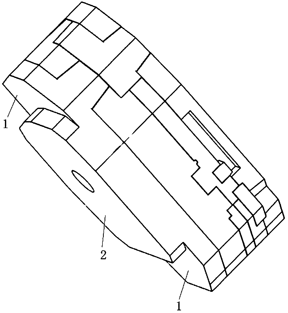
[0053] Step 2: Use three-dimensional drawing software to divide the castings with the designed gating system, and set a water glass sand molding fixing and self-locking tooling platform at the bottom of the sprue cup. The height of the platform is 80mm, such as figure 1 shown.

[0054] Step 3: According to the typing result in step...

Embodiment 2

[0067] by size Take a casting with an overall wall thickness of 10mm as an example. The material is ZL105. The casting is in the shape of a basin with a large arc and a hollow inner cavity. The required filling pressure difference is relatively large, and the large end face leads to huge filling pressure. At the same time, the cost of the 3D printing sprue sand mold is extremely high. The specific steps for its implementation are as follows:

[0068] Step 1: According to the characteristics of the casting, design the gating system, and increase the length of the sprue cup and the plane area of ​​the bottom end appropriately. Among them, the length of the sprue cup is increased to 120mm, and after increasing the bottom plane area, the distance from the edge of the sand mold to the sprue cup is not less than 220mm;

[0069] Step 2: Use three-dimensional drawing software to divide the castings with the designed gating system, and set a water glass sand molding fixing and self-l...

Embodiment 3

[0083] Taking a casting with a size of 295mm×180mm×240mm as an example, the material is ZL114A, the casting is closed in a hemispherical shape, the wall thickness of the whole body is 4mm, and it is hollow. The specific steps for its implementation are as follows:

[0084] Step 1: According to the characteristics of the casting, design the gating system, and increase the length of the sprue cup and the plane area of ​​the bottom end appropriately. Among them, the length of the sprue cup is increased to 80mm, and the bottom plane area is increased, and the distance from the edge of the sand mold to the sprue cup is not less than 160mm;

[0085] Step 2: Use three-dimensional drawing software to divide the castings with the designed gating system, and set a water glass sand molding fixing and self-locking tooling platform at the bottom of the sprue cup. The height of the platform is 70mm.

[0086] Step 3: According to the typing result in step 2, add supports to facilitate taking...


PUM


Abstract

The invention discloses an anti-gravity casting moulding method for a 3D printing sand mould. The anti-gravity casting moulding method comprises the following the steps of: designing a casting systemaccording to the characteristic of a casting; parting the casting of the designed casting system by adopting a three-dimensional map-making software, and arranging a water-glass sand mould and a self-locking workpiece placing platform at the bottom end of a pouring cup; adding support according to the parting results, adopting pre-coated sand to print sand moulding blocks added with the support, and a core, and roasting different sand moulding blocks after printing is completed; and adopting a wooden mould and water-glass sand to manufacture a pouring gate, assembling the sand mould and the water-glass sand pouring gate, jointing a self-locking tool, adopting an anti-gravity low-pressure way to cast the sand mould, thereby obtaining the casting. The anti-gravity casting moulding method solves the sand mould box-lifting problem as a result of great anti-gravity casting mould-filling pressure, enables the 3D printed sand mould to be free of phenomena such as cracks, delamination and evenbreakage, enables the dimension tolerance of the casting to reach HB6103 CT6 level, enables weight and volume deviation of the casting to be lower than or equal to 5%, and enables production cost ofthe casting to be greatly reduced.

Description

technical field [0001] The invention relates to a 3D printing sand mold anti-gravity casting forming method. The method uses anti-gravity pouring castings for casting and molding, and is suitable for the production of 3D printing sand molds and anti-gravity pouring castings. Background technique [0002] With the rapid development of the aerospace industry, more and more large and complex thin-walled structural castings are used. The current aerospace castings have the characteristics of large outline, complex structure, high mechanical performance requirements, uneven thickness and complex design of elbow oil circuit. Among the commonly used casting methods at present, anti-gravity pouring has the characteristics of stable mold filling, easy feeding, and compact structure, which can fully meet the requirements of aerospace for metallurgical quality and mechanical properties of castings. At the same time, in recent years, in order to meet the needs of scientific research pr...

Claims


Application Information

Patent Timeline
Patent Type & Authority Applications(China)
IPC IPC(8): B22D18/04B33Y10/00
CPCB22D18/04B33Y10/00
Inventor 薛祥义何益可李小军高暖周中波
Owner XIAN SUPERCRYSYAL SCI TECH DEV CO LTD
Why Eureka
Try Eureka